|
|
|
说明:双击或选中下面任意单词,将显示该词的音标、读音、翻译等;选中中文或多个词,将显示翻译。
|
|
|
1) D stress field

二维应力场
1.
For this key point in fracture study,finite element procedure and self-developed post-processing software have been applied to simulate and calculate in detail2D stress field under large scale and parameter survey condition along with pred.
针对潜山裂缝研究这一难点,采用有限元程序和自行开发的后处理软件,实现了大比例尺、参数实测条件下二维应力场的精细模拟计算和裂缝的预测评价。
2) biaxial stress

二维应力
1.
It is well known that concrete will fail in the form of cracking and sliding for the uniaxial tension and compression,the failure model can also occur in biaxial stress state,and the strength criterion that can represent the cracking and sliding is also proposed.
混凝土破坏起因于两种不同裂缝形态,即张开型裂缝和滑移型裂缝,二维应力状态下混凝土的破坏可分为拉伸破坏和剪切破坏,由此发展了一类混凝土二维强度准则模型,其参数可通过混凝土二维受压时的最大强度和相对应的应力比及受压强度影响系数确定;同时,该模型能反映混凝土破坏特征,可分别与已有强度准则和试验结果具有相近的结果,并便于工程应用。
3) 3-D stress field

三维应力场
1.
In this paper, with the help of three dimension finite element numer ical simulation method, the change of 3-D stress field in the course of current valley with seven terraces is studied by the 3-D numerical model of FEM, which c an provide a basis for the stability research .
采用三维有限元数值模拟的方法对雅砻江七级河谷阶地形成过程中应力场的变化和现今河谷阶段的三维应力场进行研究 ,为近坝库岸稳定性研究提供依据。
4) secondary stress field

二次应力场
1.
Analysis on secondary stress field characters of hard surrounding rock in large underground caverns by elasto-brittle-plastic constitutive models;
大型硬岩地下硐室围岩二次应力场特征弹脆塑性分析
2.
Taking the underground powerhouse in a huge hydropower station as an example,the authors studied distribution pattern of the secondary stress field of surrounding rock mass with nonlinear finite element method of the large-spaned underground powerhouse with high side wall and evaluated the stability of surrounding rocks.
以某大型水利工程拟建地下厂房为典型实例 ,应用二维非线性有限元分析方法 ,研究大跨度、高边墙地下厂房区二次应力场分布规律 ,并评价围岩的稳定性。
5) 2D-stresswave

二维应力波
1.
The inner decay was judged initially by the testing data of moisture content instrument and Pilodyn tester,and the distribution of inner decay in wood column was then evaluated by 2D-stresswave method.
首先通过含水率测定仪和Pilodyn检测仪初步判断了立柱可能存在的腐朽特征;再利用二维应力波方法评估了立柱内部的腐朽分布,并通过比较和分析,建立了立柱内部腐朽分布的三维仿真模型;最后采用准无损的阻抗仪方法对该三维仿真模型进行验证,确定立柱内部腐朽的准确分布,进而提出了解决方案。
6) three dimensional tectonic stress field

三维构造应力场
补充资料:铣刀片的应力场分析
【摘要】 铣削属断续切削,切削过程中刀片受力非常复杂,力的大小和方向随时变化,刀片的失效形式主要为冲击破损。因此,采用有限元法对铣刀片应力场进行分析,以寻求减少刀片破损的刀具最佳几何角度,对于铣刀片槽型的开发具有指导意义。
1.引言
铣削属断续切削,切削过程中刀片受力非常复杂,力的大小和方向随时变化,刀片的失效形式主要为冲击破损。因此,采用有限元法对铣刀片应力场进行分析,以寻求减少刀片破损的刀具最佳几何角度,对于铣刀片槽型的开发具有指导意义。 2.面铣切削加工坐标系统的建立 
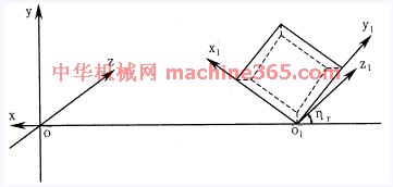
图1 面铣切削加工坐标系统
面铣切削加工坐标系统由刀体坐标系和刀片坐标系组成,如图1所示。 在刀体坐标系中,Y轴为铣刀轴线,X轴在基面内过刀尖与Y轴相交。在刀片坐标系中,y1轴通过主切削刃,x1轴通过副切削刃,刀片前刀面在x1o1y1平面内。铣刀半径为R=OO1,铣刀前角为g0,刃倾角为ls,主偏角为K,法向前角为gn。 面铣刀无论具有何种几何角度,都可看作是由刀体坐标系经过一次平移和三次旋转而成,可用矩阵表示为 
其中 A11=cosgnsinhr+singnsinlscoshr
A12=cosgncoshr-singnsinlssinhr
A13=singncosls
A21=-coslscoshr
A22=coslssinhr
A23=sinls
A31=-singnsinhr+cosgnsinlscoshr
A32=-singncoshr-cosgnsinlssinhr
A33=cosgncosls
tggn=tgg0cosls 
图2 切入冲击力的方向
3.切入冲击力方向的确定 铣削与车削的不同之处在于铣削为断续切削,存在着切入、切出过程,铣刀的破损主要是由机械冲击力引起的。因此,首先要确定铣刀切入瞬间冲击力的作用方向。铣削时,铣刀高速旋转,工件缓慢进给,若忽略进给运动(因进给运动速度仅为铣刀运动速度的约1/4),铣刀切入冲击力的方向应该在刀具相对工件运动的切线方向上。如图2所示。 由图1可知,切入冲击力方向为Z轴方向,力F分解到刀片坐标系中为 
说明:补充资料仅用于学习参考,请勿用于其它任何用途。
参考词条
|


