1) plastic zone size

塑性区尺寸
1.
The new analytical elements can be implemented into FEM program systems to compute the plastic zone sizes and crack tip opening or sliding displacement based on mode Ⅰ or mode Ⅱ D.
将该解析元与有限元相结合,构成半解析的有限元法,可求解任意几何形状和载荷的Ⅰ型或Ⅱ型裂纹基于Dugdale模型的裂纹尖端塑性区尺寸和裂纹尖端张开位移(CTOD)或裂纹尖端滑开位移(CTSD)的计算问题。
2.
In this paper, a method is proposed to estimate the plastic zone size, by extending the Dugdale model to three dimensional (3D) crack problems and the crack opening displacement (COD) at the tip of a sptatial penny shaped crack by combining the Barenblatt Dugdale model with the principle of 3D J integral, then the relationship between J integral and COD is obtained.
将Dugdale模型推广到三维裂纹问题计算了圆盘状裂纹前缘塑性区尺寸,并结合断裂力学中的Barenblat-Dugdale裂纹模型和三维J-积分原理计算了圆盘状裂纹前缘张开位移,得到了J-积分与裂纹张开位移的关系。
2) size of plastic zone
塑性区尺寸
1.
为了预测复合型裂纹呈滑移型(Ⅱ型)的断裂,在此提出了复合型裂纹扩展的最大塑性区尺寸断裂判据。
3) plastic zone size atcrack tip
裂尖塑性区尺寸
4) CTPZ size
裂纹尖端塑性区尺寸
5) plastic part size
塑件尺寸
6) Domain Size
相区尺寸
1.
formation of ion cluster and the interfacial tension between two polymers, a theoretical equation for predicting the domain size in thermoplastic interpenetrating polymer networks was derived Small-angle X-ray scattering (SAXS) techniques were applied to measure the phase dimension via statistical treatment.
从聚合物混合的热力学基础出发,推导出SBS/聚(苯乙烯-甲基丙烯酸盐)热塑性IPN的相区尺寸与其组成的理论关系式。
2.
In this paper,we report quantitative determination of interphase thickness and domain size in poly(styrene)-block-poly(butadiene) and poly(styrene)-block-poly(butadine)-block-poly(styrene) copolymers(PS-PB and PS-PB-PS) by novel solid-state NMR methods developed recently in our group.
采用我们前期发展的测定多相高聚物中界面相厚度及相区尺寸的NMR新方法对两种不同嵌段结构的聚苯乙烯-聚丁二烯嵌段共聚物进行了研究,并与关于界面相厚度的高分子物理理论结果进行对比。
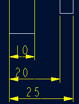
补充资料:工程图标准尺寸及坐标尺寸
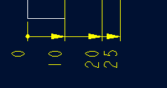
标准标注类型,是我们常用的标注类型。而坐标标注是便于数控加工采用的另一中标注形式。PRO/E可以将两种标注方式进行转换。
· 3.2 标准标注到坐标标注的转换
注意: 转化为坐标标注的尺寸必须是线性标注的,下列尺寸不能转化为坐标标注:
- 被显示成线性尺寸的直径
- 中心线尺寸
- 选择MODIFY DRAW > Dim Params > Dim Type > Ordinate Dim > Create Base.
- 选择作为参考基准线的尺寸
- 选择基准的引出线,该点为0点
- 选择 MOD DIM TYPE > Lin to Ord .
- 选择线性尺寸:注意:必须选择具有相同基准的尺寸
 ========>>>>
1. 选择 DIM PARAMS > Diam Dim Type .
2.点击Ord to Lin 
3.选择尺寸即可
说明:补充资料仅用于学习参考,请勿用于其它任何用途。
参考词条