1) cavity impression

阴模型腔
2) cavity-mode model
腔模模型
1.
In this paper, the fast algorithm based on the cavity-mode model,combined with the segmentation method, is employed to calculate the impedance characteristic of a power bus whose dielectric layer is an Electromagnetic Band-Gap(EBG) structure composed of left-handed .
本文综合运用基于腔模模型的快速算法和分解元法进行计算机仿真,研究表明由左、右手材料组合构成的电磁带隙结构能够实现理想的EMI低减,具有更加优异的性能。
3) die cavity
模具型腔
1.
The Technology for Fabricating Aspherical Plastic Lens Die Cavity;
非球面塑料透镜钢制模具型腔的加工工艺研究
2.
High performance strategy for die cavity machining oriented to tool sequence;
面向刀具序列的模具型腔高效加工策略
3.
Application of artificial neural network in tool path pattern selection for die cavity machining;
人工神经网络在模具型腔加工走刀方式选择中的应用
4) mould cavity
模具型腔
1.
Robotized magnetic abrasive finishing for mould cavity surface;
模具型腔自动化磁力研磨光整加工
2.
Discussing the method of generating mould cavity machining tool path and the layout of the tool path, illuminating the problems of tool choice at present.
本文讨论了模具型腔数控环切加工轨迹生成和规划方法,对目前刀具选择的问题进行说明,提出了刀具选择的方法,达到了加工刀具优化选择的目的,从而提高了数控加工效率。
3.
Discuss the causes of corrosion about the reinforced flame-retardant PBT to the mould cavi-ty by the analysis of the phenomenon of the mould cavity corrosion.
通过对模具型腔腐蚀现象的分析,探讨了增强阻燃PBTP对模具型腔的腐蚀原因,并提出了防腐抗腐的技术措施。
5) Cavity Mold
型腔模
1.
Application of Cimatron Software to the High Speed Machining of Cavity Mold;
Cimatron软件在型腔模具高速加工中的应用
2.
This paper introduced the cavity mold NC machining strategy in Cimatron it and the setting of associated NC parameters for typical mold part.
通过实践总结 ,归纳了使用Cimatronit进行型腔模数控加工的常用策略 ,并结合实际的应用案例介绍了典型模具零件加工工序和相关参数的设置。
6) empty space
槽腔模型
补充资料:AutoCad 教你绘制三爪卡盘模型,借用四视图来建模型
小弟写教程纯粹表达的是建模思路,供初学者参考.任何物体的建摸都需要思路,只有思路多,模型也就水到渠成.ok废话就不说了.建议使用1024X768分辨率
开始
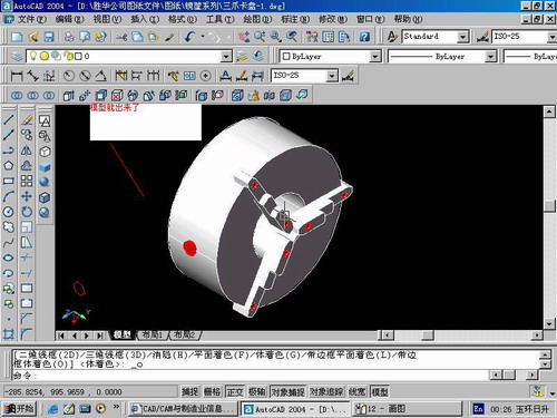
先看下最终效果

第一步,如图所示将窗口分为四个视图

第二步,依次选择每个窗口,在分别输入各自己的视图

第三步,建立ucs重新建立世界坐标体系,捕捉三点来确定各自的ucs如图
第四步,初步大致建立基本模型.可以在主视图建立两个不同的圆,在用ext拉升,在用差集运算.如图:
第五步:关键一步,在此的我思路是.先画出卡爪的基本投影,在把他进行面域,在进行拉升高度分别是10,20,30曾t形状.如图:
第六步:画出螺栓的初步形状.如图
第七步:利用ext拉升圆,在拉升内六边形.注意拉升六边行时方向与拉升圆的方向是相反的.
之后在利用差集运算
第八步:将所得内螺栓模型分别复制到卡爪上,在利用三个视图调到与卡爪的中心对称.效果如图红色的是螺栓,最后是差集
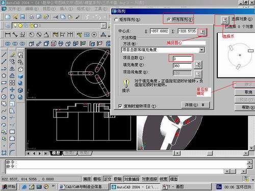
第九步:阵列
第10步.模型就完成了
来一张利用矢量处理的图片

说明:补充资料仅用于学习参考,请勿用于其它任何用途。
参考词条