1) welding heat source model


焊接热源模型
1.
Fusion welding heat source model and its trend;


熔化焊焊接热源模型及其发展趋势
2) dynamic welding heat source model


动态焊接热源模型
1.
Through analyzing the characteristics of fusion welding heat source,the welding heat source model is defined firstly,and it can be classified static welding heat source model and dynamic welding heat source model.
通过分析总结熔化焊焊接热源模型的特点,首先给出了焊接热源模型的定义,并进而提出了将焊接热源模型分类为静态焊接热源模型和动态焊接热源模型。
4) weld model


焊接模型
5) welding thermal simulation


焊接热模拟
1.
The microstructure and mechanical properties of 690 MPa grade quench and temper high-strength steel with low susceptibility to welding crack are studied under different temper heat treatment temperatures,and the welding properties of the steel are evaluated by using welding thermal simulation technology.
在不同回火热处理温度下对抗拉强度690 MPa级低焊接裂纹敏感性钢板的力学性能及组织结构进行了研究,并利用焊接热模拟技术对该钢的焊接性能进行了评估。
2.
By use of the method of welding thermal simulation, the morphology in HAZ was simulated and the post-weld heat treatment under different tempering parameter to the test specimen was carried out.
采用焊接热模拟的方法,模拟HAZ粗晶区组织,并在不同回火参数下对试样进行焊后热处理。
3.
The technological parameter of post-welded heat-treatment is determined by welding thermal simulation test.
用焊接热模拟方法确定了焊后热处理工艺参数。
6) weld thermal simulation


焊接热模拟
1.
The influence of thermal cycles on the steel enamel interface is investigated by weld thermal simulation,SEM and EMS.
采用焊接热模拟、扫描电镜、电子探针等方法研究了热循环对瓷层 /金属界面的影响 。
2.
The influence of different welding thermal circle on toughness and microstructure in the heat affected zone (HAZ) of 08MnNiVR steel was investigated by weld thermal simulation,instrumented impact toughness and metallographic test.
利用焊接热模拟、示波冲击韧性和光学金相试验,研究了不同焊接热循环对鞍钢08MnNiVR储油罐钢板热影响区组织与性能的影响。
补充资料:AutoCad 教你绘制三爪卡盘模型,借用四视图来建模型
小弟写教程纯粹表达的是建模思路,供初学者参考.任何物体的建摸都需要思路,只有思路多,模型也就水到渠成.ok废话就不说了.建议使用1024X768分辨率
开始
先看下最终效果

第一步,如图所示将窗口分为四个视图

第二步,依次选择每个窗口,在分别输入各自己的视图

第三步,建立ucs重新建立世界坐标体系,捕捉三点来确定各自的ucs如图

第四步,初步大致建立基本模型.可以在主视图建立两个不同的圆,在用ext拉升,在用差集运算.如图:

第五步:关键一步,在此的我思路是.先画出卡爪的基本投影,在把他进行面域,在进行拉升高度分别是10,20,30曾t形状.如图:

第六步:画出螺栓的初步形状.如图

第七步:利用ext拉升圆,在拉升内六边形.注意拉升六边行时方向与拉升圆的方向是相反的.
之后在利用差集运算


第八步:将所得内螺栓模型分别复制到卡爪上,在利用三个视图调到与卡爪的中心对称.效果如图红色的是螺栓,最后是差集

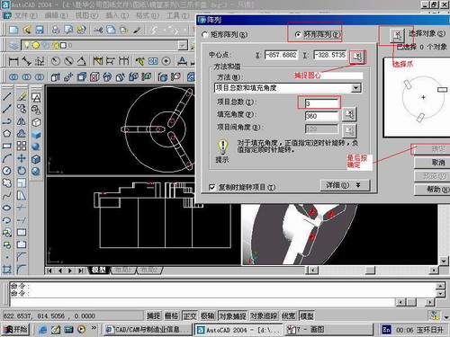
第九步:阵列

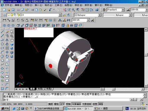
第10步.模型就完成了

来一张利用矢量处理的图片

说明:补充资料仅用于学习参考,请勿用于其它任何用途。
参考词条