1) parallel spring

平行弹簧
1.
In the normal condition,there is an assumption in the research process of equivalent stiffness coefficient of many parallel springs:the amount of compression or elongation of these parallel springs at the same time must be equal.
在通常情况下,针对多个平行弹簧等效劲度系数的研究过程中,存在这样的假设:这些平行弹簧同时被压缩或伸长的量要相等。
2) monolithic parallel spring
一体型平行弹簧
1.
The PZT used for controlling the z-axisdisplacement and the sample-to-tip distance is mounted on the monolithic parallel spring.
该系统使用一体型平行弹簧和压电致动元件(PZT)作为精密二维位置控制器件,使得x轴和y轴间的位移干扰变得极其微小。
3) double parallel and equal distance spring slices group
双平行等距弹簧片组
4) spring laming group of parallel and equal distance each other
平行等距离弹簧片组
5) spring laming group of double parallel and equal distance each other
双平行等距离弹簧片组
1.
Application of spring laming group of double parallel and equal distance each other in measuring;
双平行等距离弹簧片组在测量中的应用
6) spring balance
弹簧平衡
1.
The optimization design of electric barrier spring balance system by genetic algorithm;
利用遗传算法进行电动栏杆弹簧平衡系统的优化设计
2.
In this paper,the particularities of electric barrier design and such key technologies as optimization of internal spring balance system,the velocity and acceleration characteristics of crank-rocker mechanism,motor and decelerating system selection,self-locking scheme,high reliable and intelligent protective functions are discussed.
探讨了电动栏杆设计的特殊性和关键技术内容:内部弹簧平衡系统的优化、曲柄摇杆机构的速度和加速度特性、电机及减速系统选型、系统自锁方案、高可靠高智能的防护功能。
3.
The particularities of electric barrier design and such key technologies as optimization of internal spring balance system,the velocity and acceleration characteristics of crank-rocker mechanism,motor and decelerating system selection,system self-locking scheme and high reliable and intelligent protective functions .
本文探讨了电动栏杆设计的特殊性和关键技术内容:内部弹簧平衡系统的优化、曲柄摇杆机构的速度和加速度特性、电机及减速系统选型、系统自锁方案、高可靠高智能的防护功能。
补充资料:solidworks仿真弹簧+动画制作教程
鉴于很多朋友对这个问题一直解决不了,把教程做出来,希望望大家能够很好学习。通过本例学习,关联设计的思路和动画仿真的制作。
最终的效果:

首先建立基本零件,具体结构可以自己设定,本例采用圆柱体作为基本结构。
选择前视基准面,建立圆形草图,尺寸自己定,拉伸草图,选项如图:
由该零件生成装配体,将零件设定为浮动状态,添加配合,通过配合零件基准面和装配体基准面,固定零件1的位置。如图:
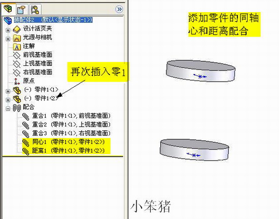
再次插入零件1,,添加同轴心配合,以及面的距离配合。如图:
插入——零件——新零件,单击装配体前视基准面定位新零件,如图:
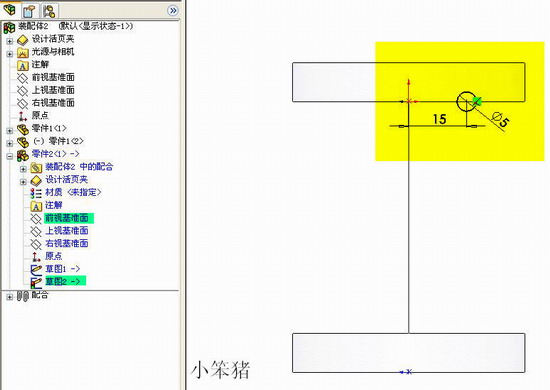
在新零件编辑界面下,选择前视基准面,绘制直线,直线的两端与一直零件边线重合。如图:
选择前视基准面,绘制草图2,。如图:
插入——特征——扫描,选项如图:
选择前视基准面,绘制矩形区域,矩形边线与已知零件边线重合,切除拉伸,选项如图:
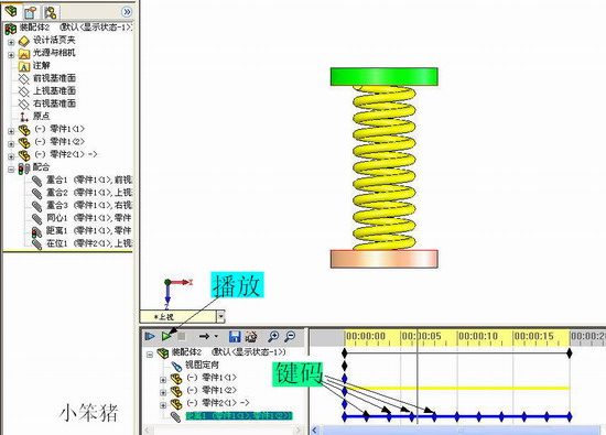
退回到装配体编辑状态,打开动画插件,如图:

为便于观察,编辑零件颜色,通过添加零件键码位置(本例之添加配合中距离的键码)。播放动画即可,动画编辑如图:
最后通过视频录制或者gif录制来查看最后效果,如图:
说明:补充资料仅用于学习参考,请勿用于其它任何用途。
参考词条