1) three-parametric model of foundation

三参数地基模型
1.
In this paper,a three-parametric model of foundation based on the Winkler-model and double-parametric model of foundation is advanced.
在Winkler地基模型和双参数地基模型基础上,提出一种三参数地基模型。
2) double parameter elastic foundation
双参数地基模型
1.
By using the model of double parameter elastic foundation in this paper the traditional method of internal force calculation .
本文利用弹性地基上的双参数地基模型理论对传统的地梁内力计算方法进行了修正,并结合结构力学中梁的挠曲线微分方程推导出梁任意截面挠度、转角、弯矩和剪力计算公式的表达式,为地梁结构设计以及进一步研究锚索预应力的力学分布规律提供了理论基础。
3) three-parameter model
三参数模型
1.
Furthermore,a three-parameter model is constructed to describe the behavior of transducers, and a Fortran code with complex least-square fitting is developed to.
进而,本文提出一个三参数模型描述传感器的行为,并发展一个复数最小二乘拟合Fortran计算方法求出数学介。
4) Fuzzy numbers of three parameters
三参数型模糊数
5) 3-parameter settlement model
三参数沉降模型
6) 3D parameterized model
三维参数化模型
1.
Aiming at the problems in automatic generating 2D drawings from 3D parameterized models,such as bad view layout,unreasonable scale,untidy dimensioning,multifarious lines,and note error,etc.
针对由三维参数化模型自动生成的工程图中视图布局较差,比例不合理,尺寸标注不整洁,线条繁杂,注释错误等缺点,根据企业给定的工程图模板及相应标准,研究了工程图模板创建与保存方法、三维模型驱动后工程图视图布局、比例、特征尺寸、焊接符号、零件序号的调整方法,以及部件图明细表的自动生成与调整方法。
2.
First builds the component and whole machine 3D parameterized models and then uses Pro/TOOLKIT and Visual C ++ to achieve the secondary development of the 3D parameterized design.
首先构建零部件和整机三维参数化模型,然后利用Pro/TOOLKIT和VisualC++实现三维参数化设计的二次开发,最后简述根据三维参数化模型生成典型零部件的工程辅助视图的机理。
补充资料:AutoCad 教你绘制三爪卡盘模型,借用四视图来建模型
小弟写教程纯粹表达的是建模思路,供初学者参考.任何物体的建摸都需要思路,只有思路多,模型也就水到渠成.ok废话就不说了.建议使用1024X768分辨率
开始
先看下最终效果

第一步,如图所示将窗口分为四个视图

第二步,依次选择每个窗口,在分别输入各自己的视图

第三步,建立ucs重新建立世界坐标体系,捕捉三点来确定各自的ucs如图
第四步,初步大致建立基本模型.可以在主视图建立两个不同的圆,在用ext拉升,在用差集运算.如图:
第五步:关键一步,在此的我思路是.先画出卡爪的基本投影,在把他进行面域,在进行拉升高度分别是10,20,30曾t形状.如图:
第六步:画出螺栓的初步形状.如图
第七步:利用ext拉升圆,在拉升内六边形.注意拉升六边行时方向与拉升圆的方向是相反的.
之后在利用差集运算
第八步:将所得内螺栓模型分别复制到卡爪上,在利用三个视图调到与卡爪的中心对称.效果如图红色的是螺栓,最后是差集
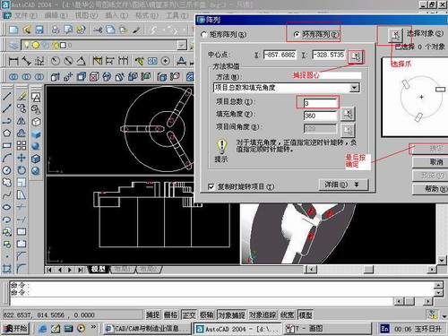
第九步:阵列
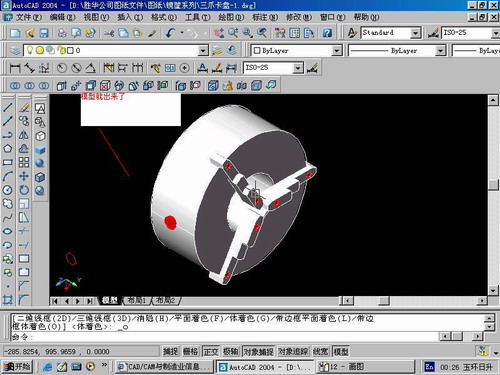
第10步.模型就完成了
来一张利用矢量处理的图片

说明:补充资料仅用于学习参考,请勿用于其它任何用途。
参考词条