1) internal function size

体内作用尺寸
1.
Inspection and computer method for internal function size is studied.
分析了体内作用尺寸与最小实体要求的相关关系,研究了体内作用尺寸的检测及计算方法,提出了不同条件下采用不同检测方法的具体措
2) external action dimension
体外作用尺寸
3) inner dimension
内尺寸
1.
The latest developments on the cylindrical inner dimension measurement with laser optical methods are introduced in this paper.
介绍了工程中用激光光学方法检测柱状结构内尺寸参数的新进展。
5) working dimension
工作尺寸
1.
Through the theoretical analysis of the two methods for calculating the working dimensions of the moulding parts of injection moulds,the theoretical defects existing in the calculation of the working dimensions by average shrinkage method and the problem existing in the actual mould design with this calculation method were pointed out.
通过对2种注射模成型零件工作尺寸计算方法的理论分析 ,指出了采用平均收缩率法存在的理论缺陷和实际模具设计中存在的问题 ,对极限公差法计算模具成型尺寸和公差作了分析和实例举证 ,说明了该计算方法能够较好地保证在注射模设计中成型尺寸和公差计算的正确性。
2.
This paper presents the principles and methods of applying microcomputer-like universal tool microscopes to measure the clearances of plain section convex and concave dies and also to calculate the working dimensions and clearances of complex section convex and concave ones in the manufacture of punching dies.
本文介绍了冲裁模制造时,应用微机型万能工具显微镜测量简单截形凸凹模的间隙以及测量复杂截形凸凹模工作尺寸与间隙的原理和方法。
6) working size
工作尺寸
1.
The working size of plastic injection moulded parts can be divided into independent working size and connective working size, so far there is no method for calculating the connective working size.
成型零件的工作尺寸可分为独立工作尺寸和关联工作尺寸,而目前尚无关联工作尺寸的计算方法。
2.
The total working size of a mould cavity is formed by the combination and accumulation of the sub-working sizes of the forming parts during the assembly process.
根据尺寸链原理,对在不同成型零件装配成模腔的过程中,由不同工作尺寸组合和累积而间接形成的工作尺寸的计算问题进行分析探讨;提出在模具设计和制造过程中,是否采用修配法来保证此类工作尺寸精度要求的判断标准及如何确定其合理的修配补偿量。
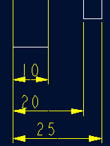
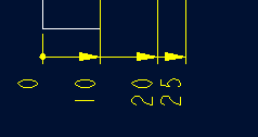
补充资料:工程图标准尺寸及坐标尺寸
标准标注类型,是我们常用的标注类型。而坐标标注是便于数控加工采用的另一中标注形式。PRO/E可以将两种标注方式进行转换。
· 3.2 标准标注到坐标标注的转换
注意: 转化为坐标标注的尺寸必须是线性标注的,下列尺寸不能转化为坐标标注:
- 被显示成线性尺寸的直径
- 中心线尺寸
- 选择MODIFY DRAW > Dim Params > Dim Type > Ordinate Dim > Create Base.
- 选择作为参考基准线的尺寸
- 选择基准的引出线,该点为0点
- 选择 MOD DIM TYPE > Lin to Ord .
- 选择线性尺寸:注意:必须选择具有相同基准的尺寸
 ========>>>>
1. 选择 DIM PARAMS > Diam Dim Type .
2.点击Ord to Lin 
3.选择尺寸即可
说明:补充资料仅用于学习参考,请勿用于其它任何用途。
参考词条