1) quadric crank mechanism


曲柄四杆机构
1.
Given the stroke speed ratio factor K of the quadric crank mechanism and the position of the two poles of the actuating driven member, using the minimum driving angle as the objective, the type and size of the quadric crank mechanism are determined with optimistic technology.
已知曲柄四杆机构的行程速比系数 K及执行从动件动点的两极限位置 ,采用最优化技术 ,以机构最小传动角最大作为寻优目标函数 ,确定曲柄四杆的类型及其尺寸。
2) crank rocker mechanism


曲柄摇杆机构
1.
Design and Analysis of Crank Rocker Mechanism in Mechanical Torsional Vibration Vibrator;


机械式扭振激振器用曲柄摇杆机构设计分析
2.
The design of crank rocker mechanism about four cylinders and four strokes inter-combustion engine with pendulous piston;
活塞摆动式内燃机曲柄摇杆机构设计
3.
Dynamic closed graph of crank rocker mechanism design;


曲柄摇杆机构设计的动态封闭图
3) Crank endplay device


曲柄-摇杆机构
4) crank-elbow bars mechanism


曲柄肘杆机构
1.
The parameters of this crank-elbow bars mechanism are given and the distinguishing features and performances of this opening-closing die mechanism are discussed.
根据920SEF模切烫金自动机合模机构的工作要求,提出了采用对称的曲柄肘杆机构作为920SEF模切烫金自动机的合模机构;并给出了该曲柄肘杆合模机构结构参数以及工作滑块(动平台)的位移与曲柄(曲轴)转角的数值关系,最后分析和总结了这种合模机构的结构特性。
5) crank-connecting rod mechanism


曲柄连杆机构
1.
Simulation research of the diesel engine crank-connecting rod mechanism on drilling;


钻井柴油机曲柄连杆机构仿真研究
2.
Analysis on characteristics of the movement and force of crank-connecting rod mechanism;


曲柄连杆机构运动及动力特性分析
3.
A dynamics mathematical model of crank-connecting rod mechanism of engine is established based on the multibody system theory, and the computer simulation program is also designed.
基于多刚体系统动力学相关理论,建立了发动机曲柄连杆机构动力学数学模型,并利用matlab软件编制了计算机仿真程序,得到了曲柄连杆机构各运动部件的运动规律及受力,为曲柄连杆机构的优化设计奠定了基础。
6) crank and rocker mechanism


曲柄摇杆机构
1.
Kinematics analysis of crank and rocker mechanism based on Matlab;


基于Matlab的曲柄摇杆机构运动分析
2.
Realization of motion simulation for crank and rocker mechanism;


曲柄摇杆机构的运动仿真实现
3.
Overall explanation and proof on three solution circle——one more discussion on auxiliary circled graphic designing method for crank and rocker mechanism;
三解圆定理的全面表述与证明——再谈曲柄摇杆机构的辅助圆图解设计法
补充资料:机械原理:曲柄滑块机构
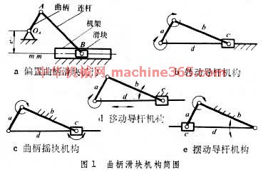
用曲柄和滑块来实现转动和移动相互转换的平面连杆机构﹐也称曲柄连杆机构。曲柄滑块机构中与机架构成移动副的构件为滑块﹐通过转动副A ﹑B 联接曲柄和滑块的构件为连杆(图1 曲柄滑块机构简图
 )。机构动动时﹐如铰链中心 B 的轨跡不通过曲柄的转动中心O ﹐称为偏置曲柄滑块机构(图1a 曲柄滑块机构简图 )﹐其中为偏距。如取不同的构件为机架﹐又可得到转动导杆机构(图1b 曲柄滑块机构简图 )﹑曲柄摇块机构(图1c 曲柄滑块机构简图 )和移动导杆机构(图1d 曲柄滑块机构简图)。如再将曲柄摇块机构中的导杆和滑块对换﹐即得到摆动导杆机构(图1e 曲柄滑块机构简图 )。如滑块B 的轨跡通过O ﹐则称为对心曲柄滑块机构(图2 对心曲柄滑块机构
 )。
)。 曲柄滑块机构广泛应用於往復活塞式发动机﹑压缩机﹑衝床等的主机构中。活塞式发动机以滑块为主动件﹐把往復移动转换为不整周或整周的迴转运动﹔压缩机﹑衝床以曲柄为主动件﹐把整周转动转换为往復移动。偏置曲柄滑块机构的滑块具有急回特性﹐锯床就是利用这一特性来达到锯条的慢进和空程急回的目的。对心曲柄滑块机构中(图2 对心曲柄滑块机构 )﹐当O A =AB 时﹐除D 点(AD =AB )的运动轨跡为直线外﹐连杆上其他点都沿椭圆轨跡运动﹐这种机构也称为椭圆仪。曲柄滑块的运动特性常用曲柄转角与滑块行程的关係曲线(图3 曲柄滑块机构简图运动特性
 )来表示。
)来表示。
说明:补充资料仅用于学习参考,请勿用于其它任何用途。
参考词条