1) eccentric tension

偏心受拉
1.
Experimental study of the behaviear of reinforced concrete members with steel fiber and bars under eccentric tension;
钢筋钢纤维混凝土偏心受拉构件受力变形性能的试验研究
2.
This paper introduces simplified commonly used calculation methods to design common bolts connection under bending moment and eccentric tension.
介绍了目前常用于设计弯矩和偏心受拉普通螺栓群连接的简化计算方法,指出了其不足之处,然后推导了其更为精确的计算方法,对弯矩和偏心受拉的普通螺栓群连接设计提出了合理建议。
3.
That is,the ligament section is simplified as eccentric tension model,and the tensile strength of f.
利用这点逆推混凝土的抗拉强度,即将韧带截面简化为偏心受拉模型,由最大荷载计算得到纤维混凝土的抗拉强度。
2) tension with large eccentricity
大偏心受拉
3) tension members with large eccentricity
大偏心受拉构件
1.
On the normal section design of doubly reinforced flexural members,tension members with large eccentricity and compression members with large eccentricity,the balanced section is designed in general,of which the equifinal depth of compression zone equals to the balanced depth of compression zone.
钢筋混凝土基本构件设计中,有两个问题值得商榷:(1)双筋受弯构件、大偏心受拉构件以及大偏心受压构件的正截面设计问题中的常见做法是在基于截面等效受压区高度等于界限高度时截面纵筋总配筋量最少的认识下将截面设计成界限截面,但根据推导,界限截面并不是纵筋总配筋量最少的条件,而且设计成界限截面还会丧失截面的延性,降低构件的可靠度。
4) eccentric tension member
偏心受拉构件
1.
The section strength for the reinforced concrete eccentric tension members is analyzed based on the traditional “plane sections remain plane” assumption (the Bernoulli′s principle) and the Code of Design of Concrete Structures(GBJ10\|89) respectively.
根据平截面假定和《混凝土结构设计规范》(GBJ10 89)所规定的基本原则 ,考虑不同的受力情况 ,分别对钢筋混凝土偏心受拉构件正截面强度进行了分析。
5) the eccentric tension-resistance bearing capacity
偏心受拉承载力
1.
This article first pointed out the formula s mistakes in the eccentric tension-resistance bearing capacity design in 《Technical Specification for Concrete structures of Tall Building》JGJ3-2002,and put forward the right form of formulas.
首先指出了《高层建筑混凝土结构技术规范》在进行墙肢正截面偏心受拉承载力设计时的公式错误,并提出了公式的正确表达式,然后对公式的正确表达式进行了合理性分析,最后对规程中墙肢在某一配筋及截面情况下只受弯矩作用时的极限抗弯承载力公式进行了合理性分析。
6) eccentric tensile loading
偏心受拉荷载
补充资料:在AutoCAD中偏心圆锥与偏心圆台实体的画法
现在要画一个偏心圆锥,底面在WCS的XY平面上,圆心(0,0,0),半径100,顶点(300,0,400)在ZX平面上.
1)连接PA,PB. A(-100,0,0) B(100,0,0)

图1
在当前坐标下:
2)延长PA到C,使PA=CA;延长PB到D,使PB=DB;
3)连接CD;
4)以CD为直径画圆;
5)用XLINE命令中的二等分选项作角CPD的角平分线PO,交CD于O;
6)过O作CD的垂线,交圆于E,F;
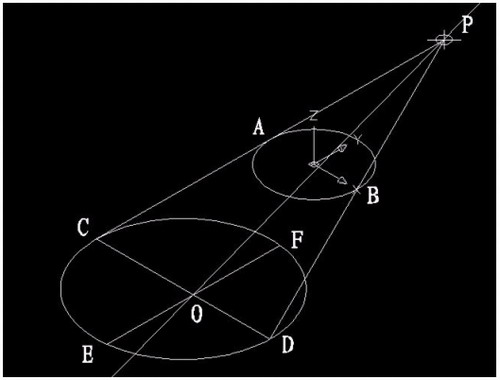
图2
7)用三点UCS命令,取三点为:O,P,C;
8)过点O作PO的垂线GO,交PC于G;

图3
9)再次用三点UCS命令,取三点为O,F,G;
10)现在就可以画椭圆锥了!
cone-e-c-捕捉O点-捕捉F点-捕捉G点-a-捕捉P点;
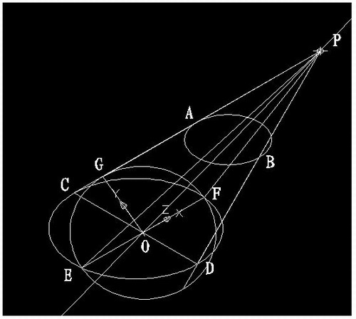
图4
11)回到WCS,剖切椭圆锥
SL-选择椭圆锥-回车-XY-回车-捕捉P点.
12)删除辅助线条.
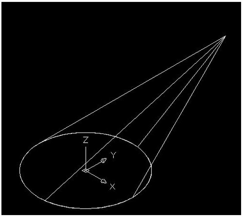
图5
说明:补充资料仅用于学习参考,请勿用于其它任何用途。
参考词条