1) stiffness eccentricity

刚度偏心
1.
The ratio spectrum distribution pattern and the effects of normalized stiffness eccentricity and rotation frequency ratio on spectrum amplitude are discussed by use of statistic analysis of 30 recordings under bidirectional earthquake excitation in the cases of hard sit.
为此,研究并建立了双向地震作用下结构刚度偏心层体系弹性反应谱模型,定义弹性位移比值谱和加速度比值谱。
2.
The effect of the system parameters on inelastic torsional response is evaluated:stiffness eccentricity es, yield strength eccentricity ep and lateral period T.
以纤维模型模拟双向地震作用下混凝土柱的双轴弯曲,考查刚度偏心es、强度偏心ep和自振周期T等因素对结构扭转的影响。
3.
Mass eccentricity and stiffness eccentricity are two key forms of asymmetric structures.
质量偏心和刚度偏心是结构偏心的两种重要形式,从单层无阻尼结构体系地震作用下的一般振动方程出发,推导得到了不同偏心形式的结构考虑地震动扭转分量时的振动方程。
2) normalized stiffness eccentricity
相对刚度偏心距
1.
The ratio spectrum distribution pattern and the effects of normalized stiffness eccentricity and rotation frequency ratio on spectrum amplitude are discussed by use of statistic analysis of 30 recordings under bidirectional earthquake excitation in the cases of hard sit.
通过对硬土、中硬(软)土、软土3类场地60条双向地震动的弹性比值谱统计平均结果,分析3类场地比值谱的谱值分布特征及相对刚度偏心距、扭转频率比对谱值及谱值分布的影响。
3) stiffness eccentricity of the isolation storey
隔震层刚度偏心距
4) stiffness eccentricity in the superstructure
上部结构刚度偏心
1.
It is shown that the influence of the mass eccentricity in the superstructure is more remarkable than that of the stiffness eccentricity in the superstructures.
本文对多层摩擦摆基础隔震上部偏心结构进行了水平双向地震作用下的平—扭耦联地震反应分析,研究了上部结构偏心对结构地震反应的影响,分析表明上部结构质量偏心比上部结构刚度偏心对摩擦摆基础隔震结构地震反应的影响较大,因而应减小上部结构质量中心与隔震层质量中心和刚度中心的偏心距,以减小结构的扭转反应;当上部结构的质量偏心距较小时,其对摩擦摆基础隔震结构的地震反应也有一定程度的影响,在结构设计应予以考虑。
6) cornering power
偏转刚度
补充资料:在AutoCAD中偏心圆锥与偏心圆台实体的画法
现在要画一个偏心圆锥,底面在WCS的XY平面上,圆心(0,0,0),半径100,顶点(300,0,400)在ZX平面上.
1)连接PA,PB. A(-100,0,0) B(100,0,0)

图1
在当前坐标下:
2)延长PA到C,使PA=CA;延长PB到D,使PB=DB;
3)连接CD;
4)以CD为直径画圆;
5)用XLINE命令中的二等分选项作角CPD的角平分线PO,交CD于O;
6)过O作CD的垂线,交圆于E,F;
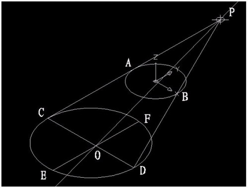
图2
7)用三点UCS命令,取三点为:O,P,C;
8)过点O作PO的垂线GO,交PC于G;

图3
9)再次用三点UCS命令,取三点为O,F,G;
10)现在就可以画椭圆锥了!
cone-e-c-捕捉O点-捕捉F点-捕捉G点-a-捕捉P点;
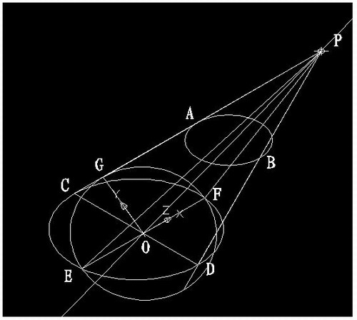
图4
11)回到WCS,剖切椭圆锥
SL-选择椭圆锥-回车-XY-回车-捕捉P点.
12)删除辅助线条.
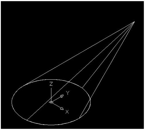
图5
说明:补充资料仅用于学习参考,请勿用于其它任何用途。
参考词条