1) active steering


主动转向
1.
Integrated Active Steering and Yaw Moment Control for Improving Vehicle Handling and Stability;
联合主动转向和横摆力矩控制的汽车操纵稳定性研究
2.
Research on Road Feeling and Active Steering Control Strategy for Vehicle Steer-By-Wire System
汽车线控转向路感模拟与主动转向控制策略研究
2) active front steering


主动转向
1.
This article introduces the configuration and function of the power steering,the wire steering and the active front steering system,and the application of the active front steering system to bus and coach.
介绍汽车转向系统的分类,以及主动转向系统的组成、原理、应用等相关情况。
3) active bogie


主动转向架
4) steering drive axle


转向主动轴
5) active front steering


主动前轮转向
1.
A method to improve braking stability by the integrated control of yaw-moment control and active front steering;
一种基于横摆力矩和主动前轮转向控制的制动稳定性控制方法
2.
A fuzzy control method is proposed to improve vehicle yaw stability by the integrated control of yaw moment control and active front steering.
提出一种基于横摆力矩和主动前轮转向相结合的车辆横向稳定性控制方法,以横摆角速度和侧偏角为控制目标,利用前馈补偿和模糊控制产生横摆力矩和附加的前轮转角,通过控制制动力的分配以及对转向角的修正,使车辆转向行驶时的横摆角速度和侧偏角很好地跟踪参考模型。
3.
The Active Front Steering System(AFS) integrates a set of dual planetary gears mechanism on the steering column between the steering wheel and rack-pinion redirector,using for providing the superposition angle to front wheel,thus realizing the variable steering ratio function.
主动前轮转向系统(Active Front Steering System,简称AFS)在转向盘和齿轮齿条转向机之间的转向柱上集成了一套双行星齿轮机构,用于向前轮提供叠加转向角,从而实现变传动比功能。
6) Active front wheel steering


主动前轮转向
1.
Then control objective and architecture for active front wheel steering system were proposed, feedforword and feedback control parts of active front wheel steering controller were designed and synthesized respectively.
建立了车辆横向动力学模型,在相平面上考察了车速、路面附着系数及前轮转角等对车辆横向稳定域的影响,提出了主动前轮转向控制系统的目标及结构,设计了横摆角速度H∞反馈和前馈控制器并进行综合。
补充资料:NX Senairo Motion 在车轮转向运动分析中的应用
前言:转向分析是开发新车新型换装车桥过程中重要的设计分析环节。现在用功能强大的UG软件作为设计分析工具提高了工作效率与工作质量,同时通过UG运动模块的动态模拟分析更便于对设计结果的验证与检查、评审。大大提高了设计的准确性,设计结果与实际产品状态非常一致。本文主要对UG运动分析模块在转向分析中的应用做详细的介绍。
运动分析模型的建立:
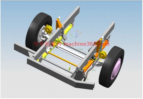
根据转向系设计参数、产品图纸对转向分析所涉及的部件进行了建模。建模部件如下:车架总成(前面部分)、前桥总成、车轮总成、转向系统各部件、前悬架系统各部件。建模如下图:

建模过程:
1.根据设计参数及零件图建立各个零件的数模,尽量做成实体。通过对转向运动特点的分析可确定哪些部件只做出外形尺寸即可不需要做其内部结构,哪些部件要做出具体的结构。这样可以简少建模时间,提高工作效率。
2.建立装配主模型。把建好的各个部件按底盘布置参数要求装配好。
3.检查及评审装配主模型,准备进入运动分析模块。
运动分析:
进入UG运动分析模块,创建机构Scenario模型如下图:

1.设置机构分析环境为动态,即调用了静力和动力学仿真分析算解器。
2.运动分析名称为默认的scenario_1。
3.进入运动分析参数预设置,改变图标比例为3,角度单位为度,设置全局重力系数如下:

因为考虑到转向分析的特点,转向纵拉杆两头由球面副连接,拉杆形状为在沿Y方向的拉杆轴平面上向内弯(为左转向轮转向运动让空间),故设置重力系数为Gy=1,以保证拉杆在运动分析过程中内弯形状一直沿Y方向。其它部件由于受运动副限制其运动不受此参数影响。(以上关于球面副运动问题,我认为软件应该有所改进,使分析过程的参数与实际情况更一致)
4.创建构件(Links)
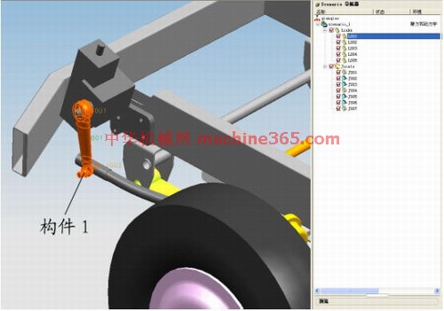
根据转向分析的需要,这里创建了5个构件。如图所示:
构件1(L001): 转向垂臂与转向纵拉杆前球头
说明:补充资料仅用于学习参考,请勿用于其它任何用途。
参考词条