1) gate location design


浇口位置设计
1.
A multi-objective optimization model for the gate location design of plastic injection molding is constructed.
建立了一个注塑模浇口位置设计的多目标优化模型,以浇口位置作为设计变量,优化充填过程中入口压力、温度分布等主要工艺参数以减小制品的翘曲程度。
2) sprue setting


浇口设置
1.
Comparative analysis was made between one and two sprue setting on the technical parameˉters,sprue pressure curve,screw speed curve,product weight,fusion seam and buckling deforˉmation.
运用MPI模拟塑料的整个注射成型过程,在不同浇口设置的条件下,从中提取填充、保压和冷却的特征过程与参数,分析对工艺造成的影响。
3) gate location


浇口位置
1.
Experiential Scouting Method:New Method of Optimization of Gate Location of Mold Design;


注塑模浇口位置优化新方法——经验搜索法
2.
Design Optimization of Plastics Injection Mold Gate Location Based on MoldFlow;


基于MoldFlow软件优化设计注塑制件的浇口位置
3.
Taking into account the great influences of gate location on part warpage,the computer aided engineering for injection molding was combined with optimization technology to find the optimal gate location with minimized feature warpage.
通过优化特征翘曲度,将数值模拟和优化技术相结合,提出一种注塑模具浇口位置设计方法。
4) gate position


浇口位置
1.
In view of the importance of gate position and quantity in the design of injection plastic molding,Moldflow,special software for analyzing the plastic flow in mold,was applied to the optimization design of gate in injection mold.
针对选择合理的浇口位置及数量在塑料模具设计中的重要性,在注塑模具设计中利用专业模流分析软件MoldFlow对模具浇口进行了优化设计。
2.
The relations of gate position to product shrinkage,gate dimension to facticity data of tensile strength and toughness of injection materials to mould cavity and ejector mechanism were stated.
简述了塑料测试试样浇口位置与制品收缩的关系,阐述了浇口尺寸与拉伸强度数据真实性的关系,以及注塑材料的韧性程度与型腔设计及顶出机构等关系,提出了解决问题的措施;还提出了从根本上解决厚制品收缩的方法——盆地修模法。
3.
The relations between gate position and injection pressure, weldline as well as part thickness in valve-typed controlled filling process are analyzed.
介绍阀式浇注控制的原理和特点,通过对浇注系统的控制充填模式研究,以注塑流动分析为理论基础,依靠CAE技术对浇注充填过程进行流动模拟,分析阀式控制的充填过程中浇口位置与注塑压力、熔接痕、制件壁厚之间的相互关系,为改善注塑工艺条件和提高注塑产品质量提供理论依据。
5) gate design


浇口设计
1.
Numerical Simulation of Plastic Part Shrinkage Rule on Gate Design of Mould;


浇口设计对塑件收缩影响规律的数值模拟研究
6) gating system plan


浇口设计;浇注系统设计
补充资料:塑胶件十大设计窍门之七浇口的位置
浇口的位置
正确的浇口位置
错误地选择浇口体系的类型和,除了会引起加工问题,还会对塑料制品的质量产生一定的影响。因而,设计部门决不能低估浇口位置的重要性。
设计者不但要进行塑料制品的设计计算,还必须特别注意模具的浇口设计。他们必须选择正确的浇口体系以及浇点的数目和位置。浇口的类型和位置不同都将对制品的质量产生较大的影响。
浇口位置的选择将决定塑料制品以下性质:
§ 填充行为
§ 制品的最终尺寸(公差)
§ 收缩行为,翘曲
§ 机械性能水平
§ 表面质量(外观)
如果设计者选择了错误的浇口,成型加工时几乎不可能从优化加工参数来矫正由此产生的后果。
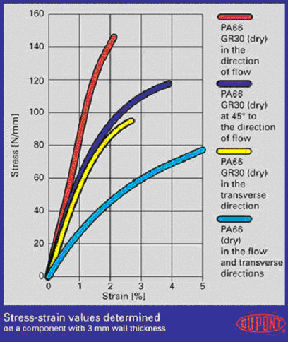
图1
制品在不同方向上的性能测定
在注射成型过程中,长链的塑料分子、纤维填料和增强材料的取向主要由熔融塑料的流动方向决定,这导致了部件性能对方向的相关性(各向异性)。例如,流动方向上的伸展性能比垂直方向上的伸展性能要好得多(见图1)。含有纤维增强材料的部件所受到的影响比不含纤维增强材料的部件要大得多。纤维的取向也引起部件在水平和垂直方向上的收缩差异,这将异致部件发生翘曲。
图2a
图2b
由于熔合线和空气存集引起部件质量下降
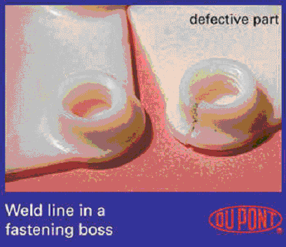
当模具中2条或更多的熔流会聚到一起时,就会产生熔合线。例如,在熔体需要流经嵌件,或制品同时在几点进行浇注时,就会出现熔合线(见图2a和2b)。而且,同一制品中不同的壁厚可能导致熔体前方分离,从而产生熔合线。当应从模具中排除的空气被熔体封闭在模具中无法溢出时,就会产生空气存集(出现气泡)。熔合线和空气存集通常被作为表面缺陷的表现。除了会使表面难看外,它们还会明显降低受影响区域的机械性能,特别是冲击强度(见图3和图4)。
图3
熔合线引起的强度降低
说明:补充资料仅用于学习参考,请勿用于其它任何用途。
参考词条