1) size of finished face


加工面尺寸
2) machining dimension


加工尺寸
1.
Based on the inspection, modeling and analysis of machining dimension, this paper proposes a new way to evaluate tool wear and life.
在对机械加工尺寸跟踪检测和对检测数据进行建模分析的基础上 ,提出对刀具磨损状况及寿命进行估计和预测的新途径 ;将加工质量控制与刀具监控统一起来 ,为自动化机械加工设备的换刀决策提供了一种新方法。
2.
Forecasting of machining dimension is the necessary requisite in machining on-line quality control, the key technique in realizing forecasting compensatory control.
加工尺寸的预报建模是进行机械加工质量在线监控的必要条件,也是实现加工误差预报补偿控制的关键技术。
3) Turning size


车加工尺寸
4) finished dimension


精加工尺寸
5) finish to size


按尺寸加工
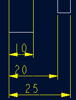
补充资料:工程图标准尺寸及坐标尺寸
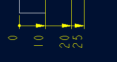
标准标注类型,是我们常用的标注类型。而坐标标注是便于数控加工采用的另一中标注形式。PRO/E可以将两种标注方式进行转换。
· 3.2 标准标注到坐标标注的转换
注意: 转化为坐标标注的尺寸必须是线性标注的,下列尺寸不能转化为坐标标注:
- 被显示成线性尺寸的直径
- 中心线尺寸
- 选择MODIFY DRAW > Dim Params > Dim Type > Ordinate Dim > Create Base.
- 选择作为参考基准线的尺寸
- 选择基准的引出线,该点为0点
- 选择 MOD DIM TYPE > Lin to Ord .
- 选择线性尺寸:注意:必须选择具有相同基准的尺寸
 ========>>>>
1. 选择 DIM PARAMS > Diam Dim Type .
2.点击Ord to Lin 
3.选择尺寸即可
说明:补充资料仅用于学习参考,请勿用于其它任何用途。
参考词条