|
|
|
说明:双击或选中下面任意单词,将显示该词的音标、读音、翻译等;选中中文或多个词,将显示翻译。
|
|
|
您的位置: 首页 -> 词典 -> 古构造应力场模拟
1) the simulation of palaeostress field

古构造应力场模拟
2) numerical simulation of tectonic stress field

构造应力场模拟
3) tectonic stress field numerical modeling

构造应力场数值模拟
4) palaeotectonic stress field

古构造应力场
1.
Present situation and prospect of application for finite element numerical simulation of palaeotectonic stress fields;
古构造应力场有限元数值模拟的应用及展望
2.
Finite element numerical simulation was applied to predicting palaeotectonic stress field distribution in buried hill reservoir on the basis of 3D fine structural interpretation and fracture description information used by structure evolution and data of outcrop, core and log.
在三维构造精细解释和综合利用构造演化、露头、岩心、测井资料描述裂缝信息的基础上,利用有限元数值模拟方法预测潜山油藏古构造应力场分布,采用格里菲斯准则和库仑摩尔准则判断张裂缝和剪裂缝的发育程度、裂缝方位及倾角。
3.
Based upon numerous and systematic joint measurement outdoors, with the help of computer, the palaeotectonic stress field of controlling the geological structure in Huangjiabao coal mine has been analysed and studied comprehensively.
通过大量的地表及井下节理测量资料,借助计算机极密统计方法,对控制该矿地质构造的古构造应力场做了较全面的分析与研究,首次恢复了该矿自中生代以来的3期构造应力场,并在此基础上,详细分析了该矿各类构造的形成机制。
5) paleotectonic stress field

古构造应力场
1.
Discussion of the paleotectonic stress field and the machanism of the structural formation in the mineral region of Doulishan;
斗笠山矿区古构造应力场及构造形成机理探讨
2.
There are many methods for fracture prediction out of which the paleotectonic stress field inversion has got more and more applications.
预测裂缝的手段较多 ,其中以边界元方法为基础的古构造应力场反演方法得到了越来越多的应用。
3.
The quantitative resumption of the paleotectonic stress field in the sedimentary basin has long been a difficult problem due to the shortage of the stress symbols.
由于缺少应力标志,沉积盆地覆盖区的古构造应力场定量恢复一直是个难题。
6) numerical simulation of 3 D tectonic stress field

三维构造应力场数值模拟
补充资料:铣刀片的应力场分析
【摘要】 铣削属断续切削,切削过程中刀片受力非常复杂,力的大小和方向随时变化,刀片的失效形式主要为冲击破损。因此,采用有限元法对铣刀片应力场进行分析,以寻求减少刀片破损的刀具最佳几何角度,对于铣刀片槽型的开发具有指导意义。
1.引言
铣削属断续切削,切削过程中刀片受力非常复杂,力的大小和方向随时变化,刀片的失效形式主要为冲击破损。因此,采用有限元法对铣刀片应力场进行分析,以寻求减少刀片破损的刀具最佳几何角度,对于铣刀片槽型的开发具有指导意义。 2.面铣切削加工坐标系统的建立 
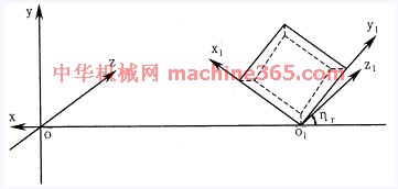
图1 面铣切削加工坐标系统
面铣切削加工坐标系统由刀体坐标系和刀片坐标系组成,如图1所示。 在刀体坐标系中,Y轴为铣刀轴线,X轴在基面内过刀尖与Y轴相交。在刀片坐标系中,y1轴通过主切削刃,x1轴通过副切削刃,刀片前刀面在x1o1y1平面内。铣刀半径为R=OO1,铣刀前角为g0,刃倾角为ls,主偏角为K,法向前角为gn。 面铣刀无论具有何种几何角度,都可看作是由刀体坐标系经过一次平移和三次旋转而成,可用矩阵表示为 
其中 A11=cosgnsinhr+singnsinlscoshr
A12=cosgncoshr-singnsinlssinhr
A13=singncosls
A21=-coslscoshr
A22=coslssinhr
A23=sinls
A31=-singnsinhr+cosgnsinlscoshr
A32=-singncoshr-cosgnsinlssinhr
A33=cosgncosls
tggn=tgg0cosls 
图2 切入冲击力的方向
3.切入冲击力方向的确定 铣削与车削的不同之处在于铣削为断续切削,存在着切入、切出过程,铣刀的破损主要是由机械冲击力引起的。因此,首先要确定铣刀切入瞬间冲击力的作用方向。铣削时,铣刀高速旋转,工件缓慢进给,若忽略进给运动(因进给运动速度仅为铣刀运动速度的约1/4),铣刀切入冲击力的方向应该在刀具相对工件运动的切线方向上。如图2所示。 由图1可知,切入冲击力方向为Z轴方向,力F分解到刀片坐标系中为 
说明:补充资料仅用于学习参考,请勿用于其它任何用途。
参考词条
|


