1) centric crank mechanism

偏置曲柄机构
2) Offset double crank mechanism
偏置双曲柄滑块机构
3) deflection crank slider mechanism
偏置式曲柄滑块机构
1.
Kinematic simulation of deflection crank slider mechanism based on simulink;
基于Simulink的偏置式曲柄滑块机构运动仿真
2.
Based on analysis of geometrical relations of deflection crank slider mechanism, this paper presents a new method of designing the mechanism using aidedstraight (circle).
在分析偏置式曲柄滑块机构几何关系的基础上,提出了一种利用辅助线(圆)设计该机构的新方法。
3.
According to the deflection crank slider mechanism, the vector loop equations of its speed and acceleration are established in this paper.
针对偏置式曲柄滑块机构,建立了速度和加速度的闭环矢量方程,使用MATLAB_Simulink对偏置式曲柄滑块机构进行了运动学仿真,得到了连杆及滑块的运动曲线。
4) offset crank and rocker mechanism
偏置型曲柄摇杆机构
1.
In the study of the positive and negative offset crank and rocker mechanism,this paper centers on the analysis of the location of the minimum transmission angle in rocker′s fast and slow travel.
本文针对正偏置和反偏置两种偏置型曲柄摇杆机构,分别分析了在摇杆快、慢行程中最小传动角的发生位置及其计算公式,并在设定曲柄为单位长度和机架相对长度d为一定值情况下,讨论了连杆和摇杆相对长度的取值可行域和机构在快、慢行程中的最小传动角等值曲线。
5) offset crank mechanism
偏置曲柄连杆机构
补充资料:机械原理:曲柄滑块机构
用曲柄和滑块来实现转动和移动相互转换的平面连杆机构﹐也称曲柄连杆机构。曲柄滑块机构中与机架构成移动副的构件为滑块﹐通过转动副A ﹑B 联接曲柄和滑块的构件为连杆(图1 曲柄滑块机构简图
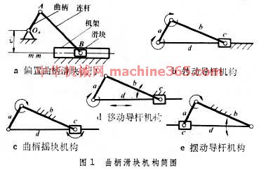 )。机构动动时﹐如铰链中心 B 的轨跡不通过曲柄的转动中心O ﹐称为偏置曲柄滑块机构(图1a 曲柄滑块机构简图 )﹐其中为偏距。如取不同的构件为机架﹐又可得到转动导杆机构(图1b 曲柄滑块机构简图 )﹑曲柄摇块机构(图1c 曲柄滑块机构简图 )和移动导杆机构(图1d 曲柄滑块机构简图)。如再将曲柄摇块机构中的导杆和滑块对换﹐即得到摆动导杆机构(图1e 曲柄滑块机构简图 )。如滑块B 的轨跡通过O ﹐则称为对心曲柄滑块机构(图2 对心曲柄滑块机构
 )。
)。 曲柄滑块机构广泛应用於往復活塞式发动机﹑压缩机﹑衝床等的主机构中。活塞式发动机以滑块为主动件﹐把往復移动转换为不整周或整周的迴转运动﹔压缩机﹑衝床以曲柄为主动件﹐把整周转动转换为往復移动。偏置曲柄滑块机构的滑块具有急回特性﹐锯床就是利用这一特性来达到锯条的慢进和空程急回的目的。对心曲柄滑块机构中(图2 对心曲柄滑块机构 )﹐当O A =AB 时﹐除D 点(AD =AB )的运动轨跡为直线外﹐连杆上其他点都沿椭圆轨跡运动﹐这种机构也称为椭圆仪。曲柄滑块的运动特性常用曲柄转角与滑块行程的关係曲线(图3 曲柄滑块机构简图运动特性
 )来表示。
)来表示。
说明:补充资料仅用于学习参考,请勿用于其它任何用途。
参考词条