1) tool eccentricity


仪器偏心率
2) tool eccentricity


仪器偏心
1.
The influences of tool eccentricity on the echoes are investigated and the experimental verification is carried out.
数字模拟和实验结果表明:仪器偏心不仅会引起回波信号幅度的变化,而且会导致频谱的改变。
3) decentralized too


偏心的仪器
4) Eccentric instrument


偏心仪
5) Eccentricity ratio


偏心率
1.
The analysis of eccentricity ratio on the steel tube concrete column;


钢管混凝土柱偏心率影响分析
2.
Based upon experiment calculation and discussion are made from two aspects: fixed pressure ratio and eccentricity ratio,at the same time resolving measures are proposed for optimum design of eccentrically compressed members,which has significant meanings for torsion-resistant design of RC eccentrically compressed members.
对钢筋混凝土偏压构件的抗扭特性进行了分析,通过实验从固定压力比和固定偏心率两个角度进行了计算和论述,提出了偏压扭构件优化设计的解决方法,对于钢筋混凝土偏压构件的抗扭设计具有十分重要的意义。
3.
When the model of the engine considered the gas pressure as load, the applied load,eccentricity ratio and friction loss of t.
首先建立了考虑气压影响的单缸发动机模型,然后通过实验测得发动机在不同环境气压下气缸内的燃气压力,将此压力作为载荷加载到单缸发动机模型上,利用AVL公司提供的商用软件EXCITEDesigner计算得出主轴承和连杆大端轴承的载荷、偏心率和摩擦功率损失。
6) eccentric ratio


偏心率
1.
With the changing of the eccentric ratio parameter of the cross section of the ellipse profile and with the extreme value principle, an analysis was made.
针对非轴对称异型材挤压塑性流动及模腔研究的理论课题 ,借助于近代共形映射数学理论研究成果和塑性成形理论 ,建立椭圆型材精密挤压模腔和金属塑性流动的三维数学模型 ,由椭圆型材截面的偏心率参数变化 ,通过能量极值原理 ,进行挤压载荷比和优化模腔参数规律性分析 ,同时为精密快速实现椭圆型材挤压模腔CAD/CAM一体化的目标提供技术支
2.
Authors analyze the characteristics of eccentric ratio of eccentric.


分析了偏心受压扣件钢管支撑偏心率的特性以及对承载能力的影响,总结了设计施工实践经验。
3.
This finite element method is employed to analyze the behavior of eccentrically loaded CFST columns,taking initial stress degree,slenderness ratio,and eccentric ratio as the parameters.
应用该方法,以长细比、偏心率和初应力度为主要参数对有初应力的钢管混凝土偏压构件进行了受力性能分析。
补充资料:在AutoCAD中偏心圆锥与偏心圆台实体的画法
现在要画一个偏心圆锥,底面在WCS的XY平面上,圆心(0,0,0),半径100,顶点(300,0,400)在ZX平面上.
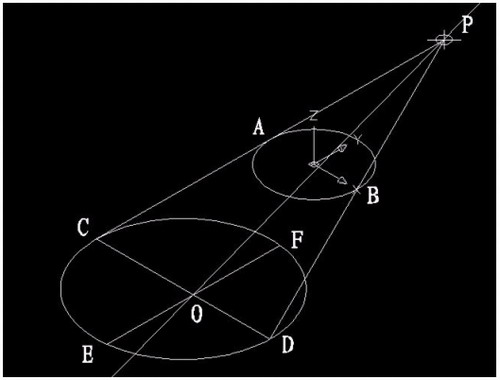
1)连接PA,PB. A(-100,0,0) B(100,0,0)

图1
在当前坐标下:
2)延长PA到C,使PA=CA;延长PB到D,使PB=DB;
3)连接CD;
4)以CD为直径画圆;
5)用XLINE命令中的二等分选项作角CPD的角平分线PO,交CD于O;
6)过O作CD的垂线,交圆于E,F;

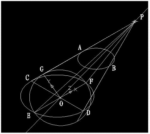
图2
7)用三点UCS命令,取三点为:O,P,C;
8)过点O作PO的垂线GO,交PC于G;

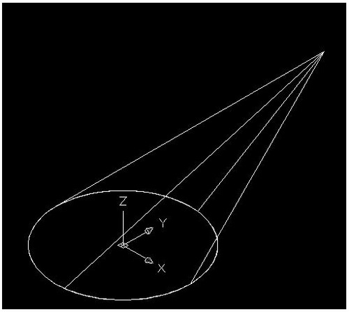
图3
9)再次用三点UCS命令,取三点为O,F,G;
10)现在就可以画椭圆锥了!
cone-e-c-捕捉O点-捕捉F点-捕捉G点-a-捕捉P点;

图4
11)回到WCS,剖切椭圆锥
SL-选择椭圆锥-回车-XY-回车-捕捉P点.
12)删除辅助线条.

图5
说明:补充资料仅用于学习参考,请勿用于其它任何用途。
参考词条