|
|
|
说明:双击或选中下面任意单词,将显示该词的音标、读音、翻译等;选中中文或多个词,将显示翻译。
|
|
|
1) five-bar linkages similar to four-bar linkages

类四杆五杆机构
1.
In this paper authors apply the idea of five-bar linkages similar to four-bar linkages to construct a two freedoms controlled six-bar linkages,and expect to improved the features of movement and dynamic of controlled linkage.
本文利用类四杆五杆机构的思想构造了一种二自由度可控六杆机构,期望通过此机构改进可控机构的运动学和动力学性能。
2) five-bar mechanism

五杆机构
1.
This paper puts forwrd a new way to research the linkage curves regulation of planar five-bar mechanism.
提出了研究平面五杆机构连杆曲线规律的新思路,采用在连杆曲线上寻找特征点定义参照系数的方法,表示连杆曲线变化情况。
2.
Based on two “similar Class Ⅱ bar groups” and “two framed links+Class Ⅱ bar groups”, this paper presents the construction methods of the basic types of the five-bar mechanism, and deduces 13 basic types of the five-bar mechanism; then the evolutionary process and characteristic of the five-bar mechanism is proposed, which is based on the selection of driving component and additive rod and so on.
提出了基于两个“类Ⅱ级杆组”和“两连架杆+Ⅱ级杆组”五杆机构的基本型构成方法,推导出五杆机构共计有13种基本型;提出了基于主动件选择、附加杆选择等五杆机构的演化过程及其特点;为五杆机构的型综合、尺度综合和选择实用可靠的机构方式提供了理论基础。
3.
A method that uses two degrees of freedom(DOF) auxiliary mechanisms to path synthesize a five-bar mechanism was presented after analyzing the posts and inverted solutions of the five-bar mechanism.
对平面二自由度五杆机构的位姿形式及位置逆解进行分析之后,提出了用二自由度辅助机构进行全铰链五杆轨迹机构综合的方法。
3) five-bar linkage

五杆机构
1.
By using the displacement equation and its singularity condition,the workspace boundary and its change rule of the plane five-bar linkage was analyzes.
以位置方程及其奇异性条件为基础,分析了五杆机构工作空间的边界特征及其演化规律。
2.
Grashof’s law for the five-bar linkage is derived by means of disassembling kinematic chains.
采用拆运动链法分析平面铰链五杆机构存在曲柄的条件,指出完全曲柄和准曲柄的区别,并分别给出它们存在的杆长条件。
4) four-bar mechanism

四杆机构
1.
Optimistic experiment methods of dimension synthesis of plane four-bar mechanism;

平面四杆机构尺度综合的优化实验法
2.
The Research of a Spatial Rolling-walk Mobile Mechanism Based on Four-bar Mechanism;

基于四杆机构的空间滚动步行移动机构研究
3.
The ant colony algorithm was used to carry on optimization design of four-bar mechanism for food machinery,analyzing and building the geometric relation between the linkage.
采用蚁群算法对食品机械四杆机构进行最优化设计,分析建立杆尺寸间的几何联系,并结合具体实例确定四杆机构各个参数。
5) four-rod mechanism

四杆机构
1.
Optimization of four-rod mechanism based on fuzzy set theory;

基于模糊集理论的四杆机构优化设计
2.
By way of analyzing the action mechanism of toys which can walk by two or four foots,the characteristics and points for attention in design of four-rod mechanisms were expounded.
四杆机构和凸轮机构在机动玩具设计中应用非常广泛,通过对两足行走和四足行走玩具动作机构分析,阐述了四杆机构在行走类玩具中的应用特点及设计注意事项。
3.
On the condition that the axes of two chain wheels are in the same horizontal plane, the paper considers that the mesh drive of chain and chain wheel is equal to single small angle movement of four-rod mechanism every time on tight side.
在两链轮的回转中心同处一水平面的条件下 ,视紧边每一时刻链条与链轮的啮合传动为四杆机构作小转角的单向运动 ,建立起相应的链条速度模型 ,并据此分析了影响链传动中链条速度波动的因素 ,得到了一些有益的结
6) Four-bar linkage

四杆机构
1.
Analysis on influence of synthetic accuracy for track of four-bar linkage affected by manufacturing error;
制造误差对四杆机构轨迹综合精度的影响分析
2.
Research on dynamic behavior of flexible four-bar linkage;

柔性四杆机构动力学行为研究
3.
The vibration test of finishing lapping machine for ball bearing outer race shows that vibration becomes more and more serious with the increasing of rotation speed of crank,which is excited by four-bar linkage.
文中提出了三种四杆机构的平衡方案,并用软件MSC。
补充资料:杆类零件机械加工CAPP

摘要: 介绍了一种基于AutoCAD软件的连杆类零件的CAPP方法,此法具有设计周期短、劳动强度小、质量高的优点。
关键词: 连杆;CAPP 连杆是一种典型的杆类零件,一般由专业制造厂或专用生产线按照严格的工艺文件,经过三、四十道工序加工完成。如用人工进行工艺过程及文件设计,则劳动强度大,设计周期长,质量不容易保证。但采用计算机辅助工艺设计(CAPP)就能克服上述缺陷。由于相同结构连杆大小头孔及中心距的不同,其加工工艺要求主要表现在尺寸和公差的变化上,这样就为实现CAPP提供了较好的工艺条件,另外,随着AutoCAD12.0以上版本中的ADS和AutoCADSQL及其扩充ASE等开发接口的出现,就更为优质快捷实现CAPP提供了良好的技术条件。
1.1 系统的原理及构成
1.1 工作原理
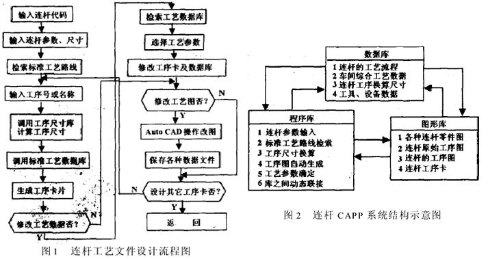
系统完全模拟工程技术人员人工设计连杆工艺过程的方法,在对某一道工序的工序卡进行自动或交互设计的过程中,完成与之有关的所有工艺文件的设计。其流程如图1所示。 1.2 总体结构
该系统由数据库、程序库及图形库组成,各库之间的数据可以动态连接,如图2所示。 2 连杆工艺数据的处理
2.1 标准工艺规程的确定
连杆的加工工艺具有很强的规律性,如把具体相同结构的连杆按型号归为一族,则他们的加工工艺路线相同,只是工艺数据和工序尺寸不同。因此当用户输入曲轴的型号后,系统即可根据这一参数在数据库中调用相应的工艺路线、工具和设备三个数据库,并从图形库中调用相应的原始工序图卡。系统中还建立了一个全面记录车间工艺数据的综合工艺数据库,以方便用户在工序卡设计中浏览,同时进行增补和修改。
2.2 工序尺寸的确定
参照连杆的幻灯片,在对话框中依次输入尺寸和公差,即可系统地得到最终的零件尺寸。根据反向编程原理,通过调用工序尺寸数据库中相应的余量和公差,计算出各个工序的加工尺寸和公差,并标注在工序图的相应位置上。工序换算尺寸库中的数据可根据连杆的类型和大小,由现场工艺师确定,同时通过数据库管理子系统还可以方便地修改或增加数据。
3 工艺数据的动态连接
3.1 标准工序卡的建立
在Auto CAD中按照连杆的形状建立标准的工序卡图形库,每一类型的标准工序为一个图文件,每一道工序的卡片占用一个以工序号为序号的图层,工序图未标注尺寸。工艺数据通过ASE为外部数据库动态连接后填写在工序卡上,首先初始化ASE,分别指定对应的标准工具、设备数据库,按照工序号搜索工具,量具和设备的数据,在卡片的相应位置以横格线为实体连接这一外部数据,并由数据加载命令写出。以这种方法写出所有图层的工艺数据,存盘退出时以图的形式保存工序卡和与外部数据库的动态连接。
说明:补充资料仅用于学习参考,请勿用于其它任何用途。
参考词条
|


