1) Interface Damage Model


界面损伤模型
2) interface damage constitutive model


界面损伤本构模
3) interfacial damage


界面损伤
1.
Analysis of stress concentrations in cross-ply (hybrid) laminates taking into account interfacial damage;
计及界面损伤的复合材料正交(混杂)叠层板的应力集中分析
2.
Based upon both the existing results of stress concentration analysis and randomly enlarging critical-core theory,a statistical analysis of the ultimate tensile failure process in cross-ply(hybrid) laminates due to the interaction of the matrix cracking in 90 degree ply,interlaminated interfacial failure,fracture of some fibers in 0 degree layers and fiber/matrix interfacial damage was performed.
基于现有应力集中分析结果及随机扩大临界核统计理论,对正交(混杂)叠层复合材料中由于90°层的基体开裂、层间界面破坏、0°层中部分纤维断裂及纤维/基体界面损伤相互作用的最终拉伸破坏过程进行统计分析。
3.
Based on the shear-lag theory, a layering shear-lag model taking into account the interfacial damage was proposed and the stress redistributions for notched cross-ply laminates under tension were analyzed, from which both the length of the interfacial damage area and stress concentration factors in intact fibers at root of the notch were obtained.
基于剪滞理论,建立了一种计及界面损伤的分层剪滞模型,分析了含割口的正交叠层板在拉伸荷载作用下的应力重新分布问题,据此可求得界面损伤区长度和割口前缘完整纤维的应力集中因子。
4) imperfect interphase


损伤界面
1.
The prediction of overall average mechanical properties for multi-phase composites with imperfect interphase;
考虑损伤界面的多相复合材料总体平均力学性能的预测
5) interface damage


界面损伤
1.
A cohesive zone model is employed to simulate the fiber/matrix interface damage of composites with ductile matrix.
用基于内聚力的界面模型分析了纤维增强韧性基体复合材料的界面损伤 ,研究了连续纤维增强复合材料受横向荷载时 ,诸如纤维排布方式、纤维体积占有率以及纤维和机体模量比等细观参数对界面损伤和材料拉伸强度的影响。
补充资料:AutoCad 教你绘制三爪卡盘模型,借用四视图来建模型
小弟写教程纯粹表达的是建模思路,供初学者参考.任何物体的建摸都需要思路,只有思路多,模型也就水到渠成.ok废话就不说了.建议使用1024X768分辨率
开始
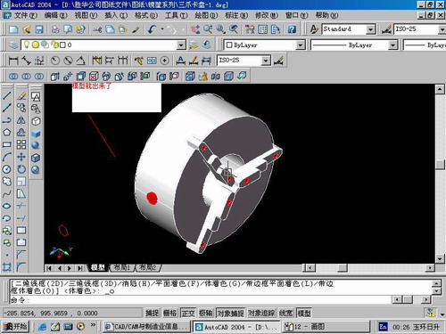
先看下最终效果

第一步,如图所示将窗口分为四个视图

第二步,依次选择每个窗口,在分别输入各自己的视图

第三步,建立ucs重新建立世界坐标体系,捕捉三点来确定各自的ucs如图

第四步,初步大致建立基本模型.可以在主视图建立两个不同的圆,在用ext拉升,在用差集运算.如图:

第五步:关键一步,在此的我思路是.先画出卡爪的基本投影,在把他进行面域,在进行拉升高度分别是10,20,30曾t形状.如图:

第六步:画出螺栓的初步形状.如图

第七步:利用ext拉升圆,在拉升内六边形.注意拉升六边行时方向与拉升圆的方向是相反的.
之后在利用差集运算


第八步:将所得内螺栓模型分别复制到卡爪上,在利用三个视图调到与卡爪的中心对称.效果如图红色的是螺栓,最后是差集

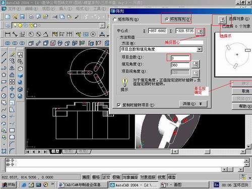
第九步:阵列

第10步.模型就完成了

来一张利用矢量处理的图片

说明:补充资料仅用于学习参考,请勿用于其它任何用途。
参考词条