1) wobbler shaft


偏心块轴
1.
The vibration, which is obtained through shock excitation electric engines driving tow symmetric wobbler shafts, makes the com.
其振动成型原理是通过激振电机驱动对称安装在振动台上的偏心块轴,产生激振力使振动台产生所需的振动,由于振动使被压实材料内产生振动冲击。
2) Eccentric block


偏心块
1.
The paper introduces three methods of calculation of eccentricity for vibratory roller s semicircleeccentric block, compares the three results of calculation with example.
介绍了振动压路机半圆形偏心块偏心矩的3种计算方法,并利用设计实例对这3种方法的计算结果进行了比较,计算误差在1%以内,并推荐使用三维软件的设计方法。
2.
According to the requirements of overall characteristics of roll leveling machine on dynamic properties of vibrating roller and through man machine interaction, the dynamic design of eccentric block in vibrating roller has been made and a more ideal structure has been found out, providing a theoretical basis for primary design of structure.
根据滚平机整机性能对振动辊动力特性的要求 ,通过人机交互方式 ,对振动辊中的激振偏心块进行了动态设计 ,找出了较理想的结构方案 ,为结构初期设计提供了理论依据。
3) eccentric shoe


偏心滑块
4) Eccentric axle


偏心轴
1.
In this paper,the formula of combustion gas pressure which act to eccentric axle of rotary engine has been given in theory.
从理论上推导了转子发动机偏心轴瞬时气动力计算公式,应用有限元技术,计算了某转子发动机偏心轴的强度,从而为偏心轴设计和定型提供依据。
5) eccentricity axis sheath


偏心轴套
6) eccentric shaft


偏心轴
1.
Forming process and dies of cold and warm extrusion for location eccentric shaft;


定位偏心轴冷温挤压成形工艺及模具
2.
Sand-belt grinding process applied to grinding the eccentric shaft of mining crusher


砂带磨削在破碎机偏心轴加工工艺上的应用
3.
Aiming at the design shortage of the vibration generator system in the quick-change dais for 4# continuous casting machine,the stub diameter of the eccentric shaft is increased from 75mm to 110mm,the transition corner radius in the root of the stub is increased from 1.
针对4#连铸机快速更换台振动发生装置原设计存在的不足,将偏心轴轴头直径由75mm加大为110mm,轴头根部过渡圆角半径由1。
补充资料:在AutoCAD中偏心圆锥与偏心圆台实体的画法
现在要画一个偏心圆锥,底面在WCS的XY平面上,圆心(0,0,0),半径100,顶点(300,0,400)在ZX平面上.
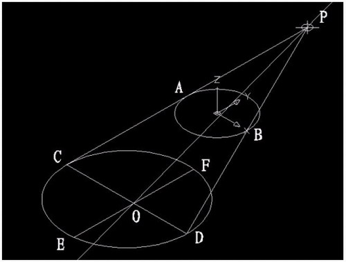
1)连接PA,PB. A(-100,0,0) B(100,0,0)

图1
在当前坐标下:
2)延长PA到C,使PA=CA;延长PB到D,使PB=DB;
3)连接CD;
4)以CD为直径画圆;
5)用XLINE命令中的二等分选项作角CPD的角平分线PO,交CD于O;
6)过O作CD的垂线,交圆于E,F;

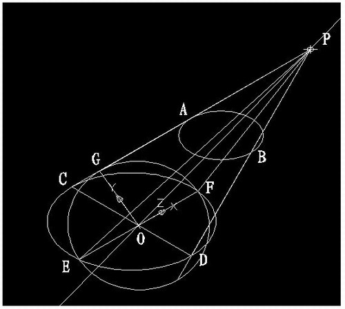
图2
7)用三点UCS命令,取三点为:O,P,C;
8)过点O作PO的垂线GO,交PC于G;

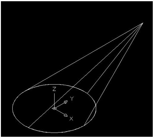
图3
9)再次用三点UCS命令,取三点为O,F,G;
10)现在就可以画椭圆锥了!
cone-e-c-捕捉O点-捕捉F点-捕捉G点-a-捕捉P点;

图4
11)回到WCS,剖切椭圆锥
SL-选择椭圆锥-回车-XY-回车-捕捉P点.
12)删除辅助线条.

图5
说明:补充资料仅用于学习参考,请勿用于其它任何用途。
参考词条