1) two shear failure model


双剪切破坏模型
2) shear failure mode


剪切型破坏
1.
The results show that the wall with shear failure mode which is considered as an advantageous mode has several anti-seismic defending lines,for the three-part members of the load-bearing system(filler blocks,concrete frame grids and concealed frame) can play a key role gradually in three stages(elastic stage,elastic-plastic stage and failure stage).
结果表明:剪切型破坏的墙体,能够按照"砌块—肋梁、肋柱—外框柱"的顺序依次发挥主导作用,具有多道抗震防线,属于有利的破坏模式;弯曲型破坏的墙体,外框柱先于墙板在柱脚发生拉压破坏,而墙板无明显破坏迹象,不易形成合理的破坏机制,属于不利的破坏模式。
3) shear failure module


剪切破坏模量
1.
Against the influencing factors of asphalt mixtures, the paper mainly analysis the changes of the shear failure module from the asphalt mixture percentage of void variety, the ratio asphalt and different gradation and different kinds of asphalt respects.
本文在分析各种试验方法及评价指标的基础上,提出采用等速率轴向局部加载试验得到的剪切破坏模量指标来评价沥青混合料高温性能。
4) Shear failure


剪切破坏
1.
Anisotropy of shear strength of layered rocks and determination of shear failure plane;


层状岩体抗剪强度的方向性及剪切破坏面的确定
2.
Research on point safety factor of shear failure geomaterials


岩土材料剪切破坏点安全系数的研究
3.
Based upon shear strain gradient plastic theory of rock deformation localization, it is assumed that the failure pattern of rock in the shear band is shear failure.
假设剪切带内部的岩体为剪切破坏 ,利用剪切应变梯度塑性理论 ,解析得出了考虑围压和孔隙压力的岩石试件应力与应变的关系 ,解析解与众多的实验研究结果比较一致 ,围压效应和孔隙压力效应是局部化所致 ,这一研究结果对于自然灾害的防治有一定的理论和实际意
5) shear breakage


剪切破坏面
1.
Based on the fact that the shear breakage of the earthwork estimated on the basis of the theory(doesn t) agree with the actual shear breakage,there is no reasonable explanation.
理论判定的土体剪切破坏面与土体实际剪切破坏面不符,且无合理解释。
6) shear failure line


剪切破坏线
补充资料:AutoCad 教你绘制三爪卡盘模型,借用四视图来建模型
小弟写教程纯粹表达的是建模思路,供初学者参考.任何物体的建摸都需要思路,只有思路多,模型也就水到渠成.ok废话就不说了.建议使用1024X768分辨率
开始
先看下最终效果

第一步,如图所示将窗口分为四个视图

第二步,依次选择每个窗口,在分别输入各自己的视图

第三步,建立ucs重新建立世界坐标体系,捕捉三点来确定各自的ucs如图

第四步,初步大致建立基本模型.可以在主视图建立两个不同的圆,在用ext拉升,在用差集运算.如图:

第五步:关键一步,在此的我思路是.先画出卡爪的基本投影,在把他进行面域,在进行拉升高度分别是10,20,30曾t形状.如图:

第六步:画出螺栓的初步形状.如图

第七步:利用ext拉升圆,在拉升内六边形.注意拉升六边行时方向与拉升圆的方向是相反的.
之后在利用差集运算


第八步:将所得内螺栓模型分别复制到卡爪上,在利用三个视图调到与卡爪的中心对称.效果如图红色的是螺栓,最后是差集

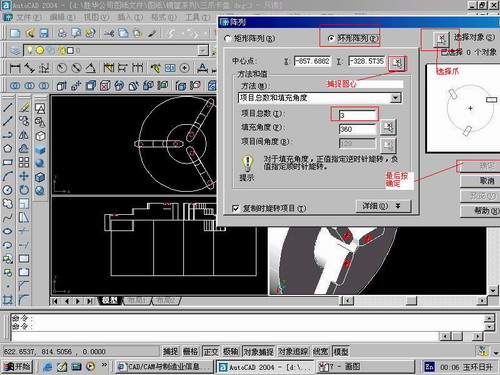
第九步:阵列

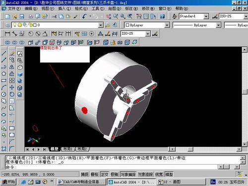
第10步.模型就完成了

来一张利用矢量处理的图片

说明:补充资料仅用于学习参考,请勿用于其它任何用途。
参考词条