1) gear side core-pulling mechanism


齿轮侧抽芯机构
1.
According the structure characteristics of the watering pot,analyzed the process of plastic molding,designed injection mold,used of the gear side core-pulling mechanism in mold structure,stated the injection mold structure design and working process.
针对洒水壶塑件的结构特点,分析了该塑件的成型工艺,并确定注射模的设计方案,在模具中巧妙地利用齿轮侧抽芯机构,并根据其特点详细论述了洒水壶塑件注射模结构设计及其工作过程。
2) side core pulling mechanism


侧抽芯机构
1.
The side core pulling mechanism of the mould is emphasized.


分析了点滴瓶瓶体的结构特点及制造工艺要求,介绍了瓶体注射模的结构及工作过程,并着重分析了该模具的侧抽芯机构,对类似模具的设计有一定的指导作用。
3) side core-pulling mechanism


侧抽芯机构
1.
Design of double side core-pulling mechanism in injection mould for the shell of circular plug socket;
壳体注射模双侧抽芯机构设计
2.
An injection mould with side core-pulling mechanism was introduced and the technology of the plastics part was analyzed.
详细阐述了模具的浇注系统、冷却系统、侧抽芯机构、顶出机构、定距分型机构、分型面选择和成型零件的设计特点及模具的工作原理,指出了模具设计、制造过程中应特别注意的问题。
3.
The location setting with flexible insert and the side core-pulling mechanism of partly molding cavity were designed, the working process of the mold was stated.
分析了带有嵌件的接线座塑件的工艺特点,介绍了适合该塑件注射模特殊结构,设计了柔性嵌件定位装置和部分型腔侧抽芯机构,并说明了该模具的工作过程。
4) gear core-pulling


齿轮抽芯
1.
Adopted manual gear core-pulling and the moving insert block core-pulling .


该模具采用了手动齿轮抽芯和活动镶块两种机构。
5) two stage side core-pulling mechanism


二级侧抽芯机构
1.
Design of two stage side core-pulling mechanism in injection mould;


塑料注射模组合式二级侧抽芯机构设计
6) side core-pulling mechanism


侧向抽芯机构
1.
At the same time,introduce the principle of side core-pulling mechanism of gear and rack injection mold, and design gist of a rack.
常用的侧向抽芯机构是斜导柱、斜滑块,当塑件上的抽芯距较长、抽芯力较大或斜向侧抽芯时,斜导柱、斜滑块抽芯比较困难,而采用齿轮、齿条就非常方便。
补充资料:抽芯成型高差大的滑块多级锁紧结构
在压铸模设计中, 常常会遇到同一抽芯而各成型高度相差较大的零件, 如果采用斜拉杆或弯销抽芯, 习惯上采取的措施是增加滑块的高度,以满足滑块的退位空间,其结果是滑块的重量增加,模框的强度降低。
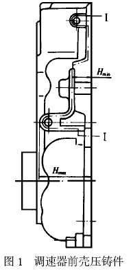
图1 是汽车油泵调速器前壳压铸件示意图, Ⅰ- Ⅰ分型面需用抽芯才能完成脱模,其最低抽芯高度Hmin 为17mm, 最大抽芯高度Hmax为45mm, 为了保证滑块有足够的退位空间而不发生自锁, 滑块的高度必须大于或等于45mm。为避免抽芯距离过大造成滑块体积增加, 在设计中采用了局部增高多级锁紧结构,如图2 所示。P 是高于17mm低于45mm的面,N是高于45mm的面,M面是与N面同高且保证N 面受力平衡的辅助结构。α为抽芯角,β1 、β2 为锁紧角,β1 、β2 不仅具有锁紧作用,而且在开模抽芯时还具有让位的作用,所以β1 、β2 必须大于α, 而且β2 应大于β1 , 否则开模时, 滑块会出现自锁。锁紧角β2 也可以等于β1 , 但由于制造时有误差, 如果误差大, 则β1和β2 形成的锁紧面会出现干涉。在压铸件调速器前壳模具设计中, α取23°, β1 取26°, β2取30°,实现了安全生产。


总之, 对于那些抽芯高度相差大的滑块,采用多级锁紧结构,对减小滑块的重量、延长模具寿命,节约模具材料具有重要的作用。
说明:补充资料仅用于学习参考,请勿用于其它任何用途。
参考词条