说明:双击或选中下面任意单词,将显示该词的音标、读音、翻译等;选中中文或多个词,将显示翻译。
您的位置:首页 -> 词典 -> 实用化技术
1)  technicae utility
实用化技术
2)  Applied optimal technologies
实用优化技术
3)  practical technique
实用技术
4)  applied technique
实用技术
1.
On that Applied Technique is the Flat Roof and Shortcut to the Rural Economy Development;
论实用技术是发展农村经济的平台和捷径
5)  practical technology
实用技术
1.
Taking TBMs and shield machines as example,the author presents the practical technology for the status monitoring and malfunction diagnosis of the equipment and machinery in the paper,which can provide reference f.
以TBM及盾构机等大型机械设备为对象,介绍机械设备状态监测与故障诊断实用技术手段和方法,希望能对应用TBM及盾构机施工的企业提供参考。
2.
Combined with the practice,the paper introduced the application of some practical technology to middle and small sized bridge.
根据多年的实践经验,介绍了钻孔灌注桩基钢筋采用冷挤压连接、宽桥面的纵横坡控制、PVC泄水管的安装等实用技术在中小桥施工中的运用。
3.
This paper, the technology and software design, introduces the practical technology about communication between a single chip microcomputer and a personal computer, which is an effectivetechnoloogy that the author explored in the work of scientific researeh.
本文从双机通讯的接口技术和软件设计出发,介绍了作者在科研实践工作中探索出的一种行之有效的双机通讯实用技术。
6)  Applied optimal design technology
实用优化设计技术
补充资料:mastercam实用技术教程二

mastercam实用技术教程4
2. 选择Boundaries设置工件毛坯。见图9-7对话框。

(1) 通过Stock项目设置工件毛坯大小。选择Parameters→Take from 2 point设置毛坯的左下角点为(-100,-310),右上角点为(100,10),生成虚线如图9-8所示的毛坯。
(2) 通过Tailstock尾座顶尖的参数。
(3) 通过Chuck设置卡盘的参数。
(4) 通过Steady rest设置辅助支撑的参数。

(5) 选择Ok,工件设置完成。
(二) 生成车端面刀具路径
1. Main Menu→Toolpaths→Face系统弹出如图9-9所示的对话框。
2.在Tool parameters参数对话框中选择刀具,并设置其他参数。
3.选择对话框中的Face parameters标签,并设置参数。见图9-10所示。Face parameters选项中各参数的含义如下:
(1)Entry amount
Entry amount输入框用于输入刀具开始进刀时距工件表面的距离
(2)Roughstepover
当选中Roughstepover输入框前面的复选框时,按该输入框设置的进刀量生成端面车削粗车刀具路径。
(3)Finish stepover
当选中Fini9hstepover输入框前面的复选框时,按该输入框设置的进刀量生成端面车削精车刀具路径。

(4)Number of finish
设置端面车削精车加工的次数。
(5)Overcut amount
该输入框用于输入在生成刀具路径时,实际车削区域超出由矩形定义的加工区域的距离。
(6)Retract amount
该输入框用于输入退刀量,当选中Rapid retract复选框时快速退刀。

(7)Stock to leave
该输入框用于输入加工后的预留量。
(8)Cut away from center
当选中该复选框时,从距工件旋转轴较近的位置开始向外加工,否则从外向内加工,
4.选择Select Point,确定加工区域。
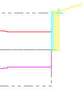
5.选择Ok,退出Face参数设置。生成如图图9-11所示的刀具路径。

二、生成轮廓粗车加工刀具路径
接着前面的例子介绍轮廓粗车加工刀具路径的生成。
1. Main Menu→Toolpaths→Rough→Chain。选取所加工的外圆柱表面,如图9-12所示。然后选择Done。

说明:补充资料仅用于学习参考,请勿用于其它任何用途。
参考词条