|
|
|
说明:双击或选中下面任意单词,将显示该词的音标、读音、翻译等;选中中文或多个词,将显示翻译。
|
|
|
1) level of stress field

应力场水平
2) Horizontal stress field

水平应力场
3) horizon field stress

水平向场应力
1.
First,it puts forward the basic method of stress analysis of excavation by boundary element program,and uses boundary element program to calculate the horizon field stress.
应用边界元法程序, 提出了巷道应力反分析的基本方法; 并根据现场的实测结果, 利用边界元法的计算机程序, 反算出地下巷道的水平向场应力, 然后把所算得的水平向场应力作为已知值返回代入边界元法程序, 求出地下巷道周边和围岩的应力、位移和破坏范围等;再据此绘制出曲线图进行分析; 最后把电算结果的巷道位移量与现场观测结果的巷道移近量进行对比。
4) horizontal stress

水平应力
1.
Physical simulation test of damage character of surrounding rock under different levels of the horizontal stress
不同水平应力作用下巷道围岩破坏特征的物理模拟试验
2.
Effect of horizontal stress and rock crack density on roof safety thickness of underground area
水平应力与裂隙密度对顶板安全厚度的影响
3.
In order to determine the effects of horizontal stress on floor heave of soft rock roadway in deep mines,the effects of different rock strength,lateral pressure coefficients and depths of notching in floor on deformation of roadway are numerically studied by means of FLAC3D software.
为了确定水平应力对深井软岩巷道底鼓的影响,采用数值模拟软件FLAC3D对不同岩性、不同侧压系数的巷道变形破坏情况及底板切槽深度对巷道变形的影响进行了研究。
5) stress level

应力水平
1.
Analysis of the effects of temperature distribution on stress level in a rotating disk;

旋转盘应力水平与温度分布的关联分析
2.
Calculation and experiment on consolidation coefficient for soft clay considering different stress levels;
考虑应力水平的软土固结系数计算与试验研究
3.
Relationship between entrance pore distribution and stress level of natural sedimentary diatomaceous soil;
天然硅藻土的应力水平与孔隙空间分布的关系
6) mean stress field

平均应力场
1.
The method for deducing mean stress field from T, B, and P axes parameters of a number of focal mechanism solutions has been verified by inverting data of mean stress fields in .
对使用多个震源机制解的T,B,P轴参数计算平均应力场的方法,以用滑动方向拟合法反演富蕴、唐山地区平均应力场数据进行验证,二者结果一致。
补充资料:铣刀片的应力场分析
【摘要】 铣削属断续切削,切削过程中刀片受力非常复杂,力的大小和方向随时变化,刀片的失效形式主要为冲击破损。因此,采用有限元法对铣刀片应力场进行分析,以寻求减少刀片破损的刀具最佳几何角度,对于铣刀片槽型的开发具有指导意义。
1.引言
铣削属断续切削,切削过程中刀片受力非常复杂,力的大小和方向随时变化,刀片的失效形式主要为冲击破损。因此,采用有限元法对铣刀片应力场进行分析,以寻求减少刀片破损的刀具最佳几何角度,对于铣刀片槽型的开发具有指导意义。 2.面铣切削加工坐标系统的建立 
图1 面铣切削加工坐标系统
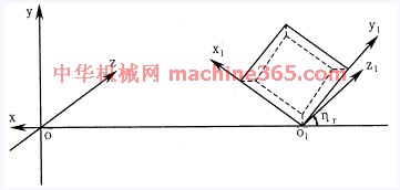
面铣切削加工坐标系统由刀体坐标系和刀片坐标系组成,如图1所示。 在刀体坐标系中,Y轴为铣刀轴线,X轴在基面内过刀尖与Y轴相交。在刀片坐标系中,y1轴通过主切削刃,x1轴通过副切削刃,刀片前刀面在x1o1y1平面内。铣刀半径为R=OO1,铣刀前角为g0,刃倾角为ls,主偏角为K,法向前角为gn。 面铣刀无论具有何种几何角度,都可看作是由刀体坐标系经过一次平移和三次旋转而成,可用矩阵表示为 
其中 A11=cosgnsinhr+singnsinlscoshr
A12=cosgncoshr-singnsinlssinhr
A13=singncosls
A21=-coslscoshr
A22=coslssinhr
A23=sinls
A31=-singnsinhr+cosgnsinlscoshr
A32=-singncoshr-cosgnsinlssinhr
A33=cosgncosls
tggn=tgg0cosls 
图2 切入冲击力的方向
3.切入冲击力方向的确定 铣削与车削的不同之处在于铣削为断续切削,存在着切入、切出过程,铣刀的破损主要是由机械冲击力引起的。因此,首先要确定铣刀切入瞬间冲击力的作用方向。铣削时,铣刀高速旋转,工件缓慢进给,若忽略进给运动(因进给运动速度仅为铣刀运动速度的约1/4),铣刀切入冲击力的方向应该在刀具相对工件运动的切线方向上。如图2所示。 由图1可知,切入冲击力方向为Z轴方向,力F分解到刀片坐标系中为 
说明:补充资料仅用于学习参考,请勿用于其它任何用途。
参考词条
|


