1) reflection losses and nonnormal incidence


斜入射和反射
1.
Based on the eye model of Kooijman,the effects of the reflection losses and nonnormal incidence of laser on the human eye s visual quality after refractive procedure on a cornea were analyzed by comparing the J.
以Kooijman眼模型为基础,根据Jimenez的理论及临床上应用的Munnerlyn理论,分析了激光在角膜前表面的斜入射和反射对角膜屈光手术后人眼成像质量的影响。
2) oblique-incldence reflectivity


斜入射反射率
3) oblique incidence


斜入射
1.
The stripes distributing of grating diffraction in conditions of oblique incidence;


斜入射光栅衍射条纹的分布
2.
An analysis of phenomenon of grating diffraction in conditions of the oblique incidence;


斜入射条件下光栅衍射现象的分析
3.
Analysis on grating's oblique incidence


关于光栅斜入射问题的分析
4) tilted incidence


倾斜入射
1.
The characteristic of thin film narrowband filters used in tilted incidence is described.
对倾斜入射时窄带薄膜滤光片的特性作了描述 ,由于低折射率间隔层的滤光片 ,倾斜入射时 p偏振分量的通带比s分量更移向短波 ,而高折射率间隔层的滤光片则反之 ,因此可把间隔层同时设计成高、低折射率两种材料 ,或选用适当的中间折射率材料 ,使p分量和s分量两个通带的中心波长重合。
2.
Compression effect of angular width for polarizing beam splitter under tilted incidence is caclulated.
从理论上计算了由于光束倾斜入射产生的棱镜起偏系统角谱宽度的压缩效应 ,计算结果表明 ,入射光束相对于棱镜入射面的入射角越大对角谱宽度的压缩就越明显 ,不同材料的基底折射率的差别对角谱宽度的压缩影响不大。
5) obliquely incident


斜入射
1.
We present a method for electromagnetic scattering with obliquely incident pulse plane wave using BOR-FDTD(body of revolution finite-difference time-domain) method.
提出一种应用时域有限差分算法求解脉冲平面波斜入射时旋转对称体散射问题的方法。
6) oblique incidence


倾斜入射
1.
Influence of substrate on shielding effectiveness of metallic mesh under oblique incidence condition;
倾斜入射条件下衬底对金属网栅屏蔽特性的影响
补充资料:AutoCAD中倒影和反射的渲染步骤
有朋友问过我渲染的方法和步骤,我也觉得这是个学习和交流的好机会,在此,我就把我的步骤简单的描述一遍,希望新手能够有点启发,高手能够给予一些指点.
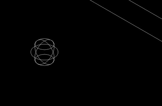
就以水晶球为例来演示:首先,绘制一个球体和一块底版,入图所示.

图1
在渲染工具栏里选择"材质",从"材质库"中选择木板和白色玻璃,分别附着在底版和球体上.选中木版材质,点击"修改".

图2
如图所示,选择"反射",将"镜像"勾上,反射值可根据效果来任意修改."确定".

图3
材质附着好后再来添加光源,以达到倒影的效果.
在渲染工具栏里选择"光源",点击"新建",我们把光源名命名问"1",再点击"修改",如图.

图4
选择"平行衰减",将"阴影打开"勾上.光源强度值可根据效果来调节.再点击"修改"来放置光源1的位置,如图:

图5
光源位置如图所示,可任意移动放置.

图6
材质附着和光源位置都完成了,现在需要修改一下"渲染"对话框的选项,点击渲染工具栏里的"渲染",如图:

图7
选择"其它选项",如图选择"高"."确定".

图8
选择"工具","选项","显示",将显示精度设置成如图数值.

图9
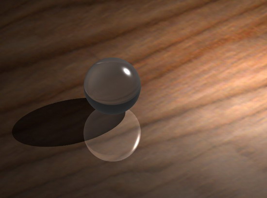
现在就可以开始渲染了,选择渲染工具栏中的"渲染","确定",等待渲染效果生成,最后效果如图:

说明:补充资料仅用于学习参考,请勿用于其它任何用途。
参考词条