1) coordinate dimension label


坐标尺寸标注
2) dimension coordinate system


尺寸标注坐标系
1.
On the basis of dimension coordinate system transformation,a new way and program example was obtained, which kept AutoCAD architectural drawing conforming to the national standard of cartography in scale transformation.
利用尺寸标注坐标系变换原理,得到了使Auto-CAD建筑图在比例变换中保持符合国家建筑制图标准的变换方法和软件实
3) dimensioning by coordinates


坐标尺寸标注法
4) coordinate dimension


坐标尺寸
1.
The calculation of the coordinate dimension of the spindlehead can be easily done.


本文介绍应用树叉图的方式来简洁、明了地表达主轴箱传动系统,它可为主轴箱的坐标尺寸计算、设计后的检查、校对、审核工作带来许多方便,特别适用于初学者的入门与掌握。
5) Size marking


尺寸标注
1.
Size marking is an important link in die design.


尺寸标注是模具设计重要实践环节,从冲压模设计尺寸标注的实际出发,讲述了冲压模具设计尺寸标注布置方法、思路、和出现的问题,实践证明效果良好,值得推广。
2.
An analysis of all kinds of common marking methods in Auto CAD2000 size marking, including more typical marking with prefix and suffix and linear marking, is presented.
通过AutoCAD 2000尺寸标注中比较典型的带前缀后缀的标注及引线标注的各种常见形式的标注方法分析,用实例说明了标注的设置、修改和处理技巧,对高效、准确、美观地完成各种尺寸标注,恰当地使用标注方式和标注设置,提高标注效率具有指导意义。
3.
It realizes intelligentize size marking of crank-shaft with Pro/Engineer and it s secondary development technology, and implements working instruction of numerical control machine and fufils CAD/CAM integration through data transmission between CAD/CAM .
应用Pro/Engineer软件及其二次开发技术,对曲轴实现智能化尺寸标注,并且通过CAD/CAM之间的数据传送,实现数控机床的加工指令,完成CAD/CAM的一体化。
6) Dimensioning
[英][di'menʃən] [美][dɪ'mɛnʃən]


尺寸标注
1.
Research of intelligent dimensioning technology based on Solid Edge’s dimension object;


基于Solid Edge尺寸对象的智能尺寸标注技术研究
2.
First,text segmentation and pixel vectorization for scanned drawing are outlined,then the dimensioning characteristics and rules for mechanical engineering drawings are analyzed,and geometry reconstructed method for dimension frame driven by text region is described.
本文在文本分割和像素矢量化的基础上,针对尺寸文本区域提出了一种尺寸标注框架的几何重建方法。
3.
Based on the analysis of the general variants of sophisticated tolerance dimensioning forms and their dimensioning methods of mechanical drawing in Auto CAD, setting skills of items under "tolerance" option are elaborated with practical examples, which will help to make a specific and artistic drawing.
通过对AutoCAD绘图中公差标注的各种常见形式的变化及其标注方法分析,用实例说明了“公差”选项卡下各个输入(选择)项的设置和处理技巧,对恰当地使用标注设置,规范、美观地完成各种公差尺寸标注具有指导意义。
补充资料:工程图标准尺寸及坐标尺寸
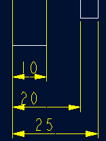
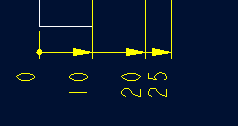
标准标注类型,是我们常用的标注类型。而坐标标注是便于数控加工采用的另一中标注形式。PRO/E可以将两种标注方式进行转换。
· 3.2 标准标注到坐标标注的转换
注意: 转化为坐标标注的尺寸必须是线性标注的,下列尺寸不能转化为坐标标注:
- 被显示成线性尺寸的直径
- 中心线尺寸
- 选择MODIFY DRAW > Dim Params > Dim Type > Ordinate Dim > Create Base.
- 选择作为参考基准线的尺寸
- 选择基准的引出线,该点为0点
- 选择 MOD DIM TYPE > Lin to Ord .
- 选择线性尺寸:注意:必须选择具有相同基准的尺寸
 ========>>>>
1. 选择 DIM PARAMS > Diam Dim Type .
2.点击Ord to Lin 
3.选择尺寸即可
说明:补充资料仅用于学习参考,请勿用于其它任何用途。
参考词条