2) migrating workflow


迁移工作流
1.
Path search and optimization in goal-oriented migrating workflow;


面向目标的迁移工作流迁移路径的寻址与优化
2.
Study on communications between MIs in migrating workflow system;


迁移工作流系统中MI间的通信研究
3.
The Model and the Frame of Migrating Workflow System;


迁移工作流系统模型及框架
3) migrating instance


迁移实例
1.
Integrity detection for migrating instance based on biology immune;


基于生物免疫的迁移实例完整性检测
2.
Efficient stage construction model to optimize migrating instance fault-tolerant execution;
优化迁移实例容错执行性能的阶段构建模型
3.
Study of Itinerary Graph Based on Task Blocks of Migrating Instance;


基于任务片的迁移实例旅行图的研究
4) Migrating Instance(MI)


迁移实例
1.
The services to Migrating Instance(MI)that a location can be offered were classified into MI services and workflow services at first,and then a service architecture based on multi-thread to support these two kinds of services was proposed in this paper.
将位置对迁移实例(MI)的服务区分为迁移实例服务和工作流服务,基于多线程设计了一种支持两类服务的体系结构,不仅有效地提高了位置服务的效率,同时增强了位置服务的可扩展性。
2.
Migrating Instance(MI) is a task executor in the migrating workflow management system,and can be cloned or derived from authorized work palaces in order to support decomposing and paralleling in business process.
迁移实例(M I)是迁移工作流管理系统中的任务执行主体,可以在授权的工作位置上克隆或派生,以支持业务过程的分解和并行。
5) instance migration


实例迁移
1.
Dynamic change model and instance migration approach for workflow management system;


工作流管理系统动态变更模型与实例迁移方法研究
2.
Workflow instance migration approach based on virtual execution rules;


一种基于虚拟执行规则的工作流实例迁移方法
3.
Workflow instance migration is a typical and important problem in the research of workflow evolution.
工作流实例迁移是工作流演化研究中典型而重要的问题。
6) workflow instance


工作流实例
1.
Second, the workflow instance can only transfer from superclass process definition to its subclass process definition.
现有的应用在跨企业工作流中的Public-To-Private(P2P)方法存在两大缺陷,一是仅能使用投影继承;二是工作流实例只能从超类过程定义向子类过程定义转换。
补充资料:分流集流阀的工作原理
分流集流阀是分流阀、集流阀和分流集流阀的总称。分流阀的作用,是使液压系统中由同一个能源向两个执行元件供应相同的流量(等量分流),以实现两个执行元件的速度保持同步或定比关系。集流阀的作用,则是从两个执行元件收集等流量或按比例的回油量,以实现其间的速度同步或定比关系。分流集流阀则兼有分流阀和集流阀的功能。它们的图形符号如图1所示。

图一、分流集流阀符号
分流阀的工作原理
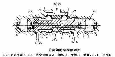
图2为等量分流阀的结构原理图。设进口油液压力为p0,流量为q0,进入阀后分两路分别通过两个面积相等的固定节流孔1、2,分别进入油室a、b,然后由可变节流口3、4经出油口I和II通往两个执行元件。如果两执行元件的负载相等,则分流口的出口压力p3=p4,因为阀中两支流道的尺寸完全对称,所以输出流量亦对称,q1=q1=q0/2,且p1=p2。当由于负载不对称而出现p3≠p4,且设p3>p4时,阀芯来不及运动而处于中间位置,由于两支流道上的总阻力相同,必定使q1

图二、等量分流阀的结构原理图
分流集流阀的工作原理
图3a为分流集流阀的结构图。阀芯5、6在各弹簧力作用下处于中间位置的平衡状态。
分流工况时,由于p0大于p1和p2,所以阀芯5和6处于相离状态,互相勾住。若负载压力p3>p4,如果阀芯仍留在中间位置,必然使p2>p1。这是连成一体的阀芯将左移,可变节流口3减小(见图3b),使p1上升,直至p1≈p2,阀芯停止运动。由于两个固定节流孔1和2的面积相等,所以通过两个固定节流孔的流量q1≈q2,而不受出口压力p3及p4变化的影响。
说明:补充资料仅用于学习参考,请勿用于其它任何用途。
参考词条