1) shaping cutting tool


成形切刀
1.
Supplied a new method for programming the machining program of the shaping cutting tool for the numerical control.
对护垫巾成形切刀试加工中存在的问题进行分析,并用QBASIC语言编制数控加工程序。
2) Tangential form tool


切向成形车刀
3) cutter assembly


切刀总成
4) form milling cutter


成形铣刀
1.
Computer aided design of form milling cutter for helicodal surface;


螺旋面成形铣刀的计算机仿真设计研究
2.
The design and simulation analysis of the staggered tooth blade cogging form milling cutter
叶片榫齿成形铣刀的错齿化设计与仿真分析
3.
The principle and device of machining logarithmic spiral profile shaft with form milling cutter are introduced.
介绍了用成形铣刀加工对数螺线型面轴的原理和装置。
5) formed milling cutter


成形铣刀
1.
The parametric design and simulation verification method for profi le of screw-formed milling cutter are introduced.
介绍了螺杆成形铣刀廓形的参数化设计及其仿真校验方法。
2.
Aiming at the design of intricate abnormity profiles of formed milling cutters,the paper presented data modeling method to design milling cutters' profile,using polynomial curve formulas with degression coordinates separating to fit the coordinates of workpiece profiles to be machined.
针对复杂不规则型面成形铣刀齿形的设计,提出用数据建模方法设计铣刀齿形。
6) formed turning tool


成形车刀
1.
NET and UG as the secondary development platform,a high precise CAD system for circular formed turning tools was developed.
NET和UG设计软件为二次开发平台,开发了高精度圆体成形车刀设计系统。
2.
And then the 3D solid model of the formed turning tool are made in accordance with the relative position between the workpiece and the tool.
利用CAD系统的三维实体造型功能 ,由工件的二维廓形生成三维实体模型 ,按照刀具和工件的相对位置关系进一步生成棱体成形车刀的三维实体模型 ,进而直接生成棱体成形车刀的廓形及其参数。
补充资料:封盖落料-拉伸-切边-成形复合模
兰州电机有限责任公司(甘肃兰州 790050) 杨思明
[摘要]分析了封盖零件的成形工艺特点,介绍了此类零件复合冲压模的结构设计。
关键词 封盖 复合模 落料 拉伸
1 零件分析
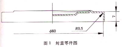
图1所示为空气滤清器的封盖,生产批量大,材料为08F,料厚0.35mm,外圆直径个80mm,拉伸高度7mm,成形后口部要求无飞边。该零件是一种典型浅盖零件,该封盖原加工工艺为落料--拉伸--压延,造成口部拉伸后有飞边,需人工清除,费力费时。
2 冲压工艺分析


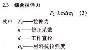
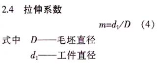
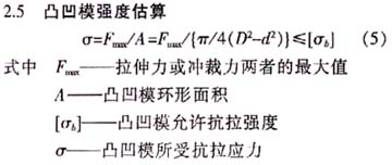
经以上计算,可一次拉伸成形,凸凹模环形壁厚强度完全可以满足要求,采用一次成形工艺为:落料--拉伸--切边--成形。
3 模具结构设计与设计要点
3.1 模具结构及其工作过程
复合棋结构如图3所示。将条料送至凹摸15上,凸凹模12下行,卸料板13压紧条料,凸凹模12与凹模15进行落料,凸凹模12继续下行,落下的圆坏料与已有压边力的压料圈5接触,拉伸凸模6与凸凹模12进行拉伸成形,凸凹模12继续下行,凸模4外圆与凸凹模12内切边模进行切边。凸凹模12再下行,拉伸凸模6与打料板7端面接触,进行压延成形。凸凹模12上行,打料板7在冲床作用下打下成品一次成形结束。
1弹簧 2顶杆 3下模座 4凸模 5压料圈 6拉伸凸模 7打料板 8卸料杆 9上模柄 10打件杆 11上模固定板 12凸凹模 13卸料板 14固定螺栓 15凹模 16下模固定板
3.2 设计要点
(1)落料凹模15内孔D尺寸计算时取最小值,在拉伸过程中试模修配拉伸凸模6圆角半径来确定切飞边量。
(2)拉伸凸模6与凸模4需设计成二个单独体,便于凸模4刃口刃磨,凸模4中心孔设计成螺纹孔便于起模。
说明:补充资料仅用于学习参考,请勿用于其它任何用途。
参考词条