1) translating follower disc cam mechanism

直动从动杆盘形凸轮机构
1.
Via introducing"comparison research"thought method and by comparing planar crank-and slider mechanism with translating follower disc cam mechanism concretally.
通过引入"比较研究"的思想方法,将平面曲柄滑块机构同直动从动杆盘形凸轮机构作具体的比较研究与探索,推导出了限制曲柄固定铰链中心点A位置的界线方程式,解决了按许用压力角设计最小尺寸的平面曲柄滑块机构的理论课题。
2) disc cam with pushing bar of roller of linear motion along the axis
对心直动滚子推杆盘形凸轮机构
1.
On the base of keeping the same law of motion of original thread-taking-up pole of computerized embroidery machine and relevant sizes,the disc cam with pushing bar of roller of linear motion along the axis with the spring force closure is used to design a new thread-taking-up mechanism.
保持原有电脑刺绣机挑线杆运动规律和相关尺寸不变,采用对心直动滚子推杆盘形凸轮机构,辅以弹簧力进行锁合,对原挑线机构进行了创新设计。
3) translation apex throwout lever disk cam organization
直动尖顶推杆盘形凸轮机构
1.
Gives an example to summarize in the machinery CAD the environment,the graphic method design translation apex throwout lever disk cam organization process,has analyzed the graphic method design precision,and compares with the traditional manual mapping.
简述在机械CAD环境下,利用图解法设计直动尖顶推杆盘形凸轮机构过程,分析了图解法设计精度,并与传统手工作图相比较,在CAD环境下的图解法设计的凸轮精度更高,更加形象直观,结果表明CAD环境下的图解法将在机械设计领域发挥重要作用。
4) translational knife-edge plate cam mechanism
直动尖顶盘形凸轮机构
1.
Take translational knife-edge plate cam mechanism for example,by analysis and research,results obtained will provide references for precision of cam mechanism.
以直动尖顶盘形凸轮机构为例,进行分析研究并得出结论,为提高凸轮机构的设计精度提供了理论依据。
5) disc cam mechanism with oscillating follower
摆动从动件盘形凸轮机构
1.
This paper points out that the traditional design method about the disc cam mechanism with oscillating follower has some shortcomings, thus it proposes one new method—using the differential method and the optimum technology to get the best parameters of the disc cam mechanism with oscillating follower.
指出了传统设计方法在确定摆动从动件盘形凸轮机构设计参数时的诸多不足,提出了一种新方法——采用微分法和最优化技术联合求解摆动从动件盘形凸轮机构的最佳设计参数。
补充资料:机械原理:凸轮机构
由凸轮的迴转运动或往復运动推动从动件作规定往復移动或摆动的机构。凸轮具有曲线轮廓或凹槽﹐有盘形凸轮﹑圆柱凸轮(图1 两种典型凸轮机构 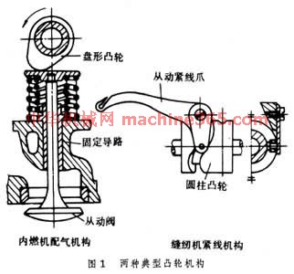 )和移动凸轮等﹐其中圆柱凸轮的凹槽曲线是空间曲线﹐因而属於空间凸轮。从动件与凸轮作点接触或线接触﹐有滚子从动件﹑平底从动件和尖端从动件等。尖端从动件能与任意复杂的凸轮轮廓保持接触﹐可实现任意运动﹐但尖端容易磨损﹐适用於传力较小的低速机构中。为了使从动件与凸轮始终保持接触﹐可採用弹簧或施加重力。具有凹槽的凸轮可使从动件传递确定的运动﹐为确动凸轮的一种。一般情况下凸轮是主动的﹐但也有从动或固定的凸轮。多数凸轮是单自由度的﹐但也有双自由度的劈锥凸轮。凸轮机构结构紧凑﹐最适用於要求从动件作间歇运动的场合。它与液压和气动的类似机构比较﹐运动可靠﹐因此在自动机床﹑内燃机﹑印刷机和纺织机中得到广泛应用。但凸轮机构易磨损﹐有噪声﹐高速凸轮的设计比较复杂﹐製造要求较高。
从动件运动规律 在带滚子的对心直动从动件盘形凸轮机构(图2 凸轮廓线设计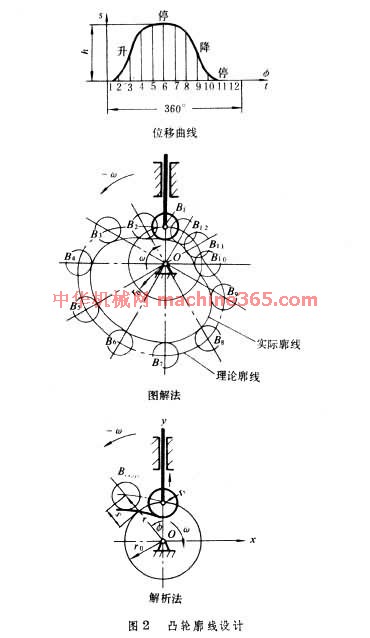 )中﹐凸轮迴转一周从动件依次作昇-停-降-停4个动作。从动件位移(或行程高度)与凸轮转角(或时间)的关係称为位移曲线。从动件的行程有推程和迴程。凸轮轮廓曲线决定於位移曲线的形状。在某些机械中﹐位移曲线由工艺过程决定﹐但一般情况下只有行程和对应的凸轮转角根据工作需要决定﹐而曲线的形状则由设计者选定﹐可以有多种运动规律。传统的凸轮运动规律有等速﹑等加速-等减速﹑餘弦加速度和正弦加速度等。等速运动规律因有速度突变﹐会產生强烈的刚性衝击﹐只适用於低速。等加速-等减速和餘弦加速度也有加速度突变﹐会引起柔性衝击﹐只适用於中﹑低速。正弦加速度运动规律的加速度曲线是连续的﹐没有任何衝击﹐可用於高速。
为使凸轮机构运动的加速度及其速度变化率都不太大﹐同时考虑动量﹑振动﹑凸轮尺寸﹑弹簧尺寸和工艺要求等问题﹐还可设计出其他各种运动规律。应用较多的有用几段曲线组合而成的运动规律﹐诸如变形正弦加速度﹑变形梯形加速度和变形等速的运动规律等﹐利用电子计算机也可以随意组合成各种运动规律。还可以採用多项式表示的运动规律﹐以获得一连续的加速度曲线。为了获得最满意的加速度曲线﹐还可以任意用数值形式给出一条加速度曲线﹐然后用有限差分法求出位移曲线﹐最后设计出凸轮廓线。
)和移动凸轮等﹐其中圆柱凸轮的凹槽曲线是空间曲线﹐因而属於空间凸轮。从动件与凸轮作点接触或线接触﹐有滚子从动件﹑平底从动件和尖端从动件等。尖端从动件能与任意复杂的凸轮轮廓保持接触﹐可实现任意运动﹐但尖端容易磨损﹐适用於传力较小的低速机构中。为了使从动件与凸轮始终保持接触﹐可採用弹簧或施加重力。具有凹槽的凸轮可使从动件传递确定的运动﹐为确动凸轮的一种。一般情况下凸轮是主动的﹐但也有从动或固定的凸轮。多数凸轮是单自由度的﹐但也有双自由度的劈锥凸轮。凸轮机构结构紧凑﹐最适用於要求从动件作间歇运动的场合。它与液压和气动的类似机构比较﹐运动可靠﹐因此在自动机床﹑内燃机﹑印刷机和纺织机中得到广泛应用。但凸轮机构易磨损﹐有噪声﹐高速凸轮的设计比较复杂﹐製造要求较高。 从动件运动规律 在带滚子的对心直动从动件盘形凸轮机构(图2 凸轮廓线设计
)中﹐凸轮迴转一周从动件依次作昇-停-降-停4个动作。从动件位移(或行程高度)与凸轮转角(或时间)的关係称为位移曲线。从动件的行程有推程和迴程。凸轮轮廓曲线决定於位移曲线的形状。在某些机械中﹐位移曲线由工艺过程决定﹐但一般情况下只有行程和对应的凸轮转角根据工作需要决定﹐而曲线的形状则由设计者选定﹐可以有多种运动规律。传统的凸轮运动规律有等速﹑等加速-等减速﹑餘弦加速度和正弦加速度等。等速运动规律因有速度突变﹐会產生强烈的刚性衝击﹐只适用於低速。等加速-等减速和餘弦加速度也有加速度突变﹐会引起柔性衝击﹐只适用於中﹑低速。正弦加速度运动规律的加速度曲线是连续的﹐没有任何衝击﹐可用於高速。 为使凸轮机构运动的加速度及其速度变化率都不太大﹐同时考虑动量﹑振动﹑凸轮尺寸﹑弹簧尺寸和工艺要求等问题﹐还可设计出其他各种运动规律。应用较多的有用几段曲线组合而成的运动规律﹐诸如变形正弦加速度﹑变形梯形加速度和变形等速的运动规律等﹐利用电子计算机也可以随意组合成各种运动规律。还可以採用多项式表示的运动规律﹐以获得一连续的加速度曲线。为了获得最满意的加速度曲线﹐还可以任意用数值形式给出一条加速度曲线﹐然后用有限差分法求出位移曲线﹐最后设计出凸轮廓线。
说明:补充资料仅用于学习参考,请勿用于其它任何用途。
参考词条