1) visual modeling/power bond graph

可视化建模/功率键合图
2) power bond graph
功率键合图
1.
Dynamics analysis of a hybrid driving five-bar linkage based on power bond graph;
基于功率键合图的混合驱动五杆机构动力学分析
2.
The application of MATLAB modeling and simulation based on power bond graph in hydraulic system;
基于功率键合图的MATLAB建模仿真在液压系统中的应用研究
3.
It used power bond graphs to get math models, and set up simulation models based on Simulink, which were encapsulated into different hydraulic component subsystems.
利用功率键合图建立液压元件的数学模型,基于Matlab/Simulink建立仿真模型,并将模型封装成子系统。
3) Power bonding diagram
功率键合图
1.
In this paper,the nolinear dynamic equations(the mathematics models)of the cone crusher hydraulicsystem are established according to the power bonding diagram.
根据功率键合图得出了圆锥破碎机液压系统的数学模型(非线性状态方程),然后给出了仿真模型,并介绍了如何用MATLAB/Simulink软件包对该液压系统的动态特性进行仿真,同时讨论了如何通过改变参数来确定影响该系统特性的主要因素。
2.
This paper inquires into the feasibility in application of the power bonding diagram method to study dynamic behaviours of a hydraulical system.
本文探讨功率键合图法对液压系统动态特性研究的可行性。
4) Power bond graphs
功率键合图
1.
Based on introducing the working course of hydraulic system of the HBT60 concrete pump and analyzing the flow characteristic of the concrete, this paper use the modeling method of the power bond graphs to establish the simulation model of the hydraulic system of concrete pump, and then run the simulation program.
本文介绍了HBT60混凝土泵液压系统工作过程,分析了混凝土的流动特征,在此基础上,用功率键合图方法建立了混凝土泵液压系统仿真模型并进行仿真。
2.
Power bond graphs was used to establish the mathematical model and MATLAB was used for digital simulation quickly.
本文采用功率键合图法建立系统数学模型,并利用MATLAB软件进行快速而准确的数字仿真,探讨系统参数对其性能的影响,对研究系统的性能和设计改进具有积极的作用。
3.
Based on the principle of power bond graphs,the modeling method for the hydraulic steering control unit type BZZ5 with the load sensing hydraulic steering system is introduced.
依据功率键合图原理,研究BZZ5型液压转向器和负荷传感全液压转向系统的建模方法。
5) Bond graph
功率键合图
1.
The method of bond graph is introduced.
介绍了功率键合图方法 ;论述了电动汽车蓄电池散热系统的热量流向并应用键合图方法建立了键合图模型 ;由键合图模型导出了数学模型并进一步建立了仿真模型 ,得到仿真结果 ,与 Advisor软件的仿真结果进行了比较分
2.
This paper expounded the application of Bond Graph and SIMULINKS tool box of MATALAB language software in the process of the analysis of dynamic characteristics of a new type of anti exploding valve.
利用功率键合图建立了一种新型防爆阀的动态特性数学模型 ,结合 SIMUL INK优秀的图形界面进行了仿真 ,提出了一种改进了的液压系统动态特性分析方
3.
This paper proposes an automated design methodology for mechatronic systems based on Genetic Programming and bond graphs.
提出一种基于遗传编程与功率键合图的机电一体化等多领域系统的自动设计方法。
6) mathematical model/power band graph
数学模型/功率键合图
补充资料:SL1126内燃机零部件数字化建模
1、 SL1126内燃机总成
SL1126内燃机是由机体总成、缸盖总成、运动机构总成,其它机构总成等组成,见图I。
(1)机体总成主要由:机体、油底壳、风扇、油标、同步齿轮室盖、主副曲轴轴承盖、标尺及相应的标准零件。在机体总成中,机体是主要的设计零件。
(2)气缸盖总成主要包括的零件有:气缸盖、缸盖罩、喷油嘴、机油筒、空气滤清器等零件;其中气缸盖是主要设计零件。
(3)运动机构总成由活塞,滑块,活塞销,连杆,连杆配件,主、副曲轴总成,正视齿轮总成,凸轮轴总成以及气门挺杆总成等组成。
(4)其他机构总成有:机油泵总成,喷油泵总成等组成。
SL1126内燃机是由机体总成、缸盖总成、运动机构总成,其它机构总成等组成,见图I。
(1)机体总成主要由:机体、油底壳、风扇、油标、同步齿轮室盖、主副曲轴轴承盖、标尺及相应的标准零件。在机体总成中,机体是主要的设计零件。
(2)气缸盖总成主要包括的零件有:气缸盖、缸盖罩、喷油嘴、机油筒、空气滤清器等零件;其中气缸盖是主要设计零件。
(3)运动机构总成由活塞,滑块,活塞销,连杆,连杆配件,主、副曲轴总成,正视齿轮总成,凸轮轴总成以及气门挺杆总成等组成。
(4)其他机构总成有:机油泵总成,喷油泵总成等组成。
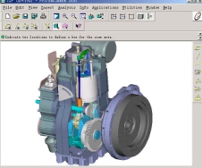
图I SL1126内燃机总成
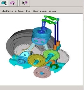
图II 内燃机运动机构总成
2、自顶向下设计的参数化技术
在CAD中,参数化技术是采用参数预定义的方法建立图形的集合约束集,指定一组尺寸作为参数使其与几何约束集相关联,并将所有的关联式融入到应用程序中,然后以人机交互方式修改参数尺寸,通过参数化尺寸驱动实现对设计结果的修改。参数化设计过程中,参数与设计对象的控制尺寸有明显的对应关系,并具有全局相关性。参数化设计不同于传统的设计,它储存了设计的整个过程,能设计出一族而非单一的在形状和功能上具有相似性的产品模型。正是有了这种参数化建模技术,才使得数据的改变在不同层次(如不同的子装配系统和不同的零件)之间的传递变得唯一个即时。这样,才有了真正意义上的自顶向下设计及以这种设计为基础的并行设计,后者是团队设计的基础。
下面以主同步齿轮零件三维参数化为例:
下面为渐开线方程:
alpha=20
m=4
z=46
r0=0.5*m*z*cos(20)
t0=t*40
x0=(cos(t0)+t0*pi/180*(sin(t0)))*r0
y0=(sin(t0)-t0*pi/180*(cos(t0)))*r0
theta=-(tan(alpha)-alpha*pi/180)*180/pi-90/z
x=x0*cos(theta)-y0*sin(theta)
y=x0*sin(theta)+y0*cos(theta)
z=0
其中alpha为压力角, m为模数, z为齿数, r0为基圆半径。

图III 齿轮总成
说明:补充资料仅用于学习参考,请勿用于其它任何用途。
参考词条