1) three-dimensional model of four-bar mechanism


四杆机构的空间模型
2) space four bar linkage mechanism


空间四连杆机构
3) spatial four-bar mechanism


空间四杆机构
1.
The Research of a Smart Mobile Platform Based on Spatial Four-bar Mechanism;


基于空间四杆机构的灵巧移动平台研究
2.
A single spatial four-bar mechanism with two degrees of freedom is adopted as the body of the biped mechanism.
该步行机构以单一的两自由度空间四杆机构作为本体,与传统的多杆多动力步行机构相比,具有结构与控制系统简单的优点。
4) RSSP spatial four bar mechanism


RSSP空间四杆机构
1.
In this paper, according to travel velocity ratio cofficient k and maximum travel h of slider, a model for optimal design of RSSP spatial four bar mechanism by minimizing the maximum pressure angle is presented.
按已知的行程速比系数 k,滑块的最大行程 h,对 RSSP空间四杆机构进行优化设计 ,使该机构的最大压力角 αmax趋于最小 ,并给出了实例。
5) spatial mechanism


空间连杆机构
1.
In this paper, through analyzing the Fourier expansion of coupler curves of the spatial mechanism, the problem of the mathematic representation of the coupler curves has been resolved by using the Fast Fourier transform (in short, FFT).
从空间连杆机构连杆曲线的Fourier级数表达式入手,解决了空间连杆机构连杆曲线的数学描述问题。
6) spatial linkages


空间连杆机构
1.
A practical method for approximate balancing of shaking force and shaking moment of spatial linkages is proposed by attaching counter weights to frame pivoted links.
提出了通过在连架构件上附加质量配重实现空间连杆机构摆动力与摆动力矩近似平衡的方法 。
2.
A practical method for approximate shaking force balancing of spatial linkages is proposed by attaching counter weights to frame pivoted links.
提出了通过在连架构件上附加质量配重实现空间连杆机构摆动力近似平衡的方法。
3.
A kind of designing scheme of double PSSR spatial linkages is proposed for the bottom door mechanism of bulk cargo warehouse,the working principle is analyzed,and its mathematical model is established.
提出了一种可用于散粒货物仓库底开门机构的双PSSR型空间连杆机构的设计方案,分析其工作原理,建立了数学模型。
补充资料:AutoCad 教你绘制三爪卡盘模型,借用四视图来建模型
小弟写教程纯粹表达的是建模思路,供初学者参考.任何物体的建摸都需要思路,只有思路多,模型也就水到渠成.ok废话就不说了.建议使用1024X768分辨率
开始
先看下最终效果

第一步,如图所示将窗口分为四个视图

第二步,依次选择每个窗口,在分别输入各自己的视图

第三步,建立ucs重新建立世界坐标体系,捕捉三点来确定各自的ucs如图

第四步,初步大致建立基本模型.可以在主视图建立两个不同的圆,在用ext拉升,在用差集运算.如图:

第五步:关键一步,在此的我思路是.先画出卡爪的基本投影,在把他进行面域,在进行拉升高度分别是10,20,30曾t形状.如图:

第六步:画出螺栓的初步形状.如图

第七步:利用ext拉升圆,在拉升内六边形.注意拉升六边行时方向与拉升圆的方向是相反的.
之后在利用差集运算


第八步:将所得内螺栓模型分别复制到卡爪上,在利用三个视图调到与卡爪的中心对称.效果如图红色的是螺栓,最后是差集

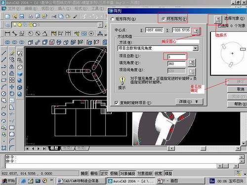
第九步:阵列

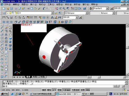
第10步.模型就完成了

来一张利用矢量处理的图片

说明:补充资料仅用于学习参考,请勿用于其它任何用途。
参考词条