|
|
|
说明:双击或选中下面任意单词,将显示该词的音标、读音、翻译等;选中中文或多个词,将显示翻译。
|
|
|
1) adding line

补线
1.
The classifying method was used to describe the implementation of matching and checking of adding line style of composite solid by computer in details.
采用分类方法 ,对在计算机上实现组合体补线题目的匹配校验问题进行了较为详细的讨论 ,提出了校验机制的设计思路 ,并给出了相应的检验算法 。
2) Linear interpolation
直线插补
1.
Algorithm for linear interpolation of four coordinates with point-by-point comparison method;
基于逐点比较法的四坐标联动直线插补算法
2.
Linear interpolation control and its realization based on PLC;
基于PLC的直线插补控制及其实现
3.
Design and Realization of Linear Interpolation Controller Based on CPLD
基于CPLD的直线插补控制器的设计与实现
3) Line interpolation
直线插补
1.
A brief and fast new line interpolation arithmetic is proposed in this article.
文章介绍了一种简捷的快速直线插补新算法,两个坐标轴可实现同时进给,插补速度较快,均匀性好,偏差判别式的计算方法简单。
2.
This paper studies the algorithm improvement for the general method of line interpolation.
本文对传统的数控直线插补方法进行了算法改进 ,使插补过程中各坐标轴分配的脉冲序列保持均匀 ,以克服步进电机失步问题 ,提高了插补精
3.
To satisfy the high speed,high precision,high efficiency and high reliability of CNC system,a new line interpolation controller was designed in this paper.
为满足数控系统的高速度、高精度、高效率和高可靠性,设计了一种新型直线插补控制器。
4) linear interpolation
线性插补
1.
Meanings of linear interpolation and velocity;
多轴联动线性插补及其速度的理解
2.
This article analyzed the theoretical errors resulted from approximating the perfect continuous tool path with linear interpolation in 5-axis machining,and this kind of error is also called non-linear motion errors or known as the geometry-based errors.
分析了五坐标联动数控系统采用线性五轴插补运动时,与实际的空间非线性连续轨迹之间的理论加工误差;用空间解析几何、齐次坐标变换建立了双转台结构五坐标机床的运动变换数学模型,并结合五坐标数控机床加工过程的线性插补原理,建立了该类五坐标机床的非线性运动误差估计模型,提出了一种非线性误差控制策略。
3.
To overcome this problem and optimize machining speed,based on the data sampling method,the 5-axis simultaneous linear interpolation was realized by using the equivalent displacement and the directional coefficient of the coordinate axis.
基于数据采样法,利用当量位移和坐标轴方向系数实现了5轴联动线性插补;利用直线加减速原理进行插补前加减速控制;对速度前瞻控制方法进行了深入探讨,实现了相邻程序段转接处速度优化、连续微小程序段速度计算、减速点提前预测及前瞻程序段数动态选择等。
5) curve interpolation
曲线插补
1.
The algorithm simplified the complicated calculation in the usual course of B_spline curve interpolation, expedited the interpolation of B_spline curve, and has very important value in the real_time interpolation.
该方法简化了通常B样条曲线插补过程中的繁琐计算 ,提高了B样条曲线的插补速度 ,在B样条曲线的实时插补中具有非常重要的实际意义。
2.
In order to achieve high speed and precision work,and on the basis of three times NURBS curve analyzing,NURBS curve interpolation algorithm principle is proposed.
为实现数控机床高速度高精度加工,在分析三次NURBS曲线原理的基础上,提出NURBS曲线插补算法原理。
3.
This paper introduces the use of NURBS(Non- Uniform Rational B- Spline) in CNC(Computerized Numerical Control)curve interpolation.
本文详细介绍数控系统的NURBS(Non-Uniform Rational B-Spline)曲线插补技术。
6) cycloid interlude
摆线插补
补充资料:CAXA-V2线切割软件在DK7725e线切割机床上的应用
目前我国有大量的装有早期操作系统的数控设备,如何对其进行升级使这些设备重新焕发青春是摆在大家面前的一个很重要的问题。本文所介绍的正是这样的一个实例,文中所叙述的内容不仅对同类设备的改造具有现实意义,而且对其他类似设备的升级也有一定的借鉴作用。 苏州三光的DK7725e线切割机床的操作系统是基于DOS平台上的,而CAXA-V2线切割软件是在Windows 98平台上开发的应用软件。显然,我们无法直接将CAXA-V2线切割软件安装到DK7725e线切割机床的操作系统中。解决这一问题的关键是寻找二者的共同之处,那就是机床的后置处理和传输功能单元,即G代码程序。 一、CAXA-V2线切割软件方面的操作 1.进入绘图界面 在装有CAXA-V2线切割软件的计算机桌面上点击图标,进入该软件的绘图界面。 2.绘制零件图
在软件的绘图区域中绘制线切割加工零件图,如图1所示。
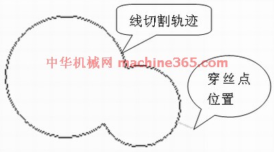
图1 线切割加工零件 3.生成加工轨迹 利用“轨迹生成”指令,生成线切割加工零件的加工轨迹,同时确定穿丝点位置和补偿量。 4.添加后置处理 由于CAXA-V2线切割软件并未提供DK7725e线切割机床的“后置处理和传输”,需要手工添加,具体操作过程如下: (1)点击CAXA-V2线切割软件的“后置处理和传输”图标,绘图区会弹出一个对话框。
(2)选中“增加机床”图标,在弹出的对话框中用键盘输入“BKDC”后,按确定键返回,如图2所示。
(3)在“后置处理和传输”的对话框中,按苏州三光的DK7725e线切割机床的“后置处理和传输”参数,手工输入相应的参数和指令,如图3所示。


图3 机床类型设置
(4)在“后置处理和传输”的对话框中点击“后置处理设置”后,相应地也会弹出一个对话框。该对话框中的参数要求也按苏州三光的DK7725e线切割机床的“后置处理设置”参数来设置,如图4所示。
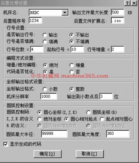
图4 后置处理设置 5.生成G代码 完成上述设置后,点击“代码生成”指令,选择“G代码生成”后,再选中线切割加工零件的加工轨迹,该轨迹图线将由绿色变为红色,最后点击鼠标右键,弹出记事本对话框显示相应的G代码加工程序,如图5所示。
说明:补充资料仅用于学习参考,请勿用于其它任何用途。
参考词条
|