1) off center load compensation


偏心负载补偿
1.
In this paper, compensation techniques of seismic simulation system are introduced primarily, including geometric cross coupling compensation, overturning movement compensation, off center load compensation and force balance compensation.
对振动台控制技术的台面补偿技术作了初步研究分析,其中包含几何交叉耦合补偿、倾覆力矩(OTM)补偿、偏心负载补偿和力平衡补偿,并分析了它们的原理和电路实现原理框图。
2) eccentricity compensation


偏心补偿
1.
Based on eccentricity control principle and eccentricity signal model,an eccentricity compensation project for single stand and reversing cold strip mill was studied.
在深入分析轧辊偏心对板带材厚度影响的基础上,从偏心控制原理和偏心信号模型入手,研究了一种单机架可逆冷轧机轧辊偏心补偿方案。
2.
The effect principle which roller eccentricity affect strip gauge was analyzed,and eccentricity compensation control dynamic structural map which apply Fast Fourier Transport(FFT)method was established.
分析了冷轧带钢轧机偏心补偿控制的机理,建立了通过傅立叶分析提取偏心信号基波分量作为控制量的偏心补偿动态结构图。
3.
To reduce the influence of roll eccentricity on thickness of strip,a method of roll eccentricity compensation based on RBF network is introduced which has been used on 5-stand cold tandem mill at Hebei Zhonggang Group.
轧辊偏心是影响轧制过程中带材厚度精度的重要因素,因此轧辊的偏心补偿控制一直是冷轧板厚度控制系统AGC的重要组成部分。
3) eccentric load


偏心负载
1.
Weight estimation of rotor eccentric load based on acceleration sensor;


基于加速度传感器的转子偏心负载质量估算
2.
Real-time rotor eccentric load locating based on acceleration sensor;


基于加速度传感器的转子偏心负载实时定位
3.
Effects of eccentric load on dynamic characteristics of pneumatic rotary cylinder and countermeasures
偏心负载对摆动气缸动特性影响及抑制措施
4) compensating of load


负载力补偿
5) load compensating


载荷补偿;负载力补偿
6) load dynamic compensation


负载动态补偿
1.
In addition, for the X-drift asynchronous problem caused by Y-drift tool position variation, load dynamic compensation is proceeded.
此外,还针对Y轴方向上的由于刀架位置变化导致的X轴方向上的不同步进行了负载动态补偿。
补充资料:在AutoCAD中偏心圆锥与偏心圆台实体的画法
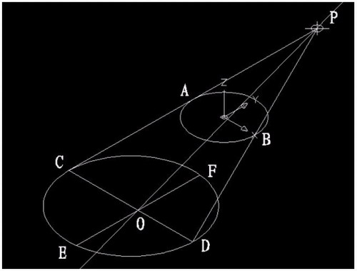
现在要画一个偏心圆锥,底面在WCS的XY平面上,圆心(0,0,0),半径100,顶点(300,0,400)在ZX平面上.
1)连接PA,PB. A(-100,0,0) B(100,0,0)

图1
在当前坐标下:
2)延长PA到C,使PA=CA;延长PB到D,使PB=DB;
3)连接CD;
4)以CD为直径画圆;
5)用XLINE命令中的二等分选项作角CPD的角平分线PO,交CD于O;
6)过O作CD的垂线,交圆于E,F;

图2
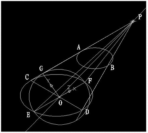
7)用三点UCS命令,取三点为:O,P,C;
8)过点O作PO的垂线GO,交PC于G;

图3
9)再次用三点UCS命令,取三点为O,F,G;
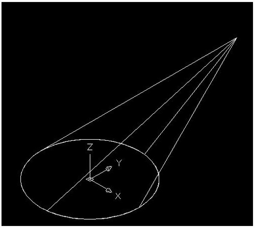
10)现在就可以画椭圆锥了!
cone-e-c-捕捉O点-捕捉F点-捕捉G点-a-捕捉P点;

图4
11)回到WCS,剖切椭圆锥
SL-选择椭圆锥-回车-XY-回车-捕捉P点.
12)删除辅助线条.

图5
说明:补充资料仅用于学习参考,请勿用于其它任何用途。
参考词条