1) polarization interference

偏振干涉
1.
Fiber grating sensor demodulation method based on polarization interference
基于偏振干涉的光纤光栅传感解调方法
2.
The sensor demodulation system of the polarization-maintaining fiber loop mirror based on polarization interference was designed and established.
研究了基于保偏光纤的光纤环镜结构并建立理论模型,分析各参数之间的关系,设计并搭建了基于偏振干涉的保偏光纤环镜传感解调系统。
2) polarization interferometric
偏振干涉
1.
A new reflect-polarization interferometric electronic current transformer was developed and tested.
提出了一种新的反射式偏振干涉电流互感器,建立了系统的结构模型,阐述了互感器的工作原理,给出了λ/4延迟器产生圆偏振光的方法和传感头的设计方案,最后给出了实验数据。
3) Polarization interferometer
偏振干涉仪
1.
Through spectral slicing by using a polarization interferometer(PI),the multi-wavelength pulses are obtained and can be aligned as a higher repeat frequency pulse source with proper wavelength spacing due to the dis.
通过一个偏振干涉仪(PI)进行光谱切片,形成多波长脉冲。
4) polarized light interference
偏振光干涉
1.
Performance of Lyot crystal-type depolarizer is analyzed with the help of Jones vector and polarized light interference principle in frequency domain.
运用琼斯矢量及偏振光干涉的原理,从频域的角度分析Lyot晶体型消偏器的性能,得到消偏器的设计判据:第一个晶体的厚度等于真空中光源的相干长度比晶体的双折射率。
2.
The article introduces an advanced approach to fiber grating wavelength demodulation based on the principle of polarized light interference.
提出一种先进的基于偏振光干涉的光纤光栅解调实现方法 ,偏振光干涉仪也是一种能将布拉格波长移动转化为干涉相位变化的非平衡干涉仪。
3.
A new structure of polarized light interference interleaver is presented.
提出了一种偏振光干涉型光交错复用器的新结构。
5) Polarization interference
偏振光干涉
1.
A new structure of tunable polarization interference dense wavelength division multiplexing (DWDM) filter based on the analog birefringent module is presented.
提出了一种基于模拟双折射模块的可调谐偏振光干涉型密集波分复用滤波器(DWDM)的新结构。
6) interference of polarization
偏振干涉法
补充资料:偏振光的干涉
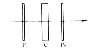
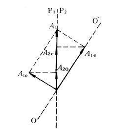
| 偏振光的干涉 polarized light,interference of 线偏振光叠加后产生的干涉 。D.F.J.阿拉戈和A.J.菲涅耳于1816年利用杨氏干涉装置做了最早的偏振光干涉实验,对确立光的横波性有重要意义。偏振光的干涉通常利用各向异性的晶片来实现。如图1,P1和P2是两平行放置的偏振片(或其他起偏器),它们的偏振化方向互相垂直(称正交偏振片)。以自然光垂直入射,若两偏振片间无各向异性物体,则光不能通过P2 ;若在两者间插进各向异性的晶片C,则将有光通过P2,光源为白光时,在P2后还能观察到绚丽的色彩,这是偏振光干涉的结果,称显色偏振。
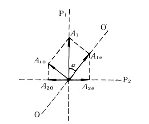
设晶片光轴OO′与其表面平行,从P1透出的线偏振光的振幅为A1,振动方向与晶片光轴夹a 角,在晶片中将分解成传播方向相同的o光和e光(见双折射),振幅分别为A10和A1e,它们的振方向互相垂直 。从晶片透出的两振动只有与P2的偏振化方向平行的分量才能通过P2,两振幅分量为A20=A2e = A1sinacosa ,振动方向沿同一直线(图2),相位差为 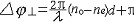 于是产生干涉。上式中d为晶片厚度,π是由于投影引起的相位差。若P1和P2的偏振化方向互相平行(称平行偏振片),振动的投影情况如图3 。参与相干叠加的两振动一般有不同的振幅,相位差为 于是产生干涉。上式中d为晶片厚度,π是由于投影引起的相位差。若P1和P2的偏振化方向互相平行(称平行偏振片),振动的投影情况如图3 。参与相干叠加的两振动一般有不同的振幅,相位差为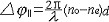 从P2透出的光的干涉强度由相位差决定,对一定的晶片,干涉强度与波长λ有关。光源用白光时,有些波长达干涉极大,另一些波长达干涉极小,故呈现一定的色彩,称为干涉色。转动晶片或任一偏振片,色彩将跟着变化。若晶片厚度或主折射率不均匀,将出现不同干涉色的分布。以会聚的线偏振光入射到晶片时,将产生具有特殊形状的干涉图样,通过对干涉图样的分析可确定晶体的光轴取向。 从P2透出的光的干涉强度由相位差决定,对一定的晶片,干涉强度与波长λ有关。光源用白光时,有些波长达干涉极大,另一些波长达干涉极小,故呈现一定的色彩,称为干涉色。转动晶片或任一偏振片,色彩将跟着变化。若晶片厚度或主折射率不均匀,将出现不同干涉色的分布。以会聚的线偏振光入射到晶片时,将产生具有特殊形状的干涉图样,通过对干涉图样的分析可确定晶体的光轴取向。
偏振光的干涉普遍用于对岩石晶体的鉴别和分析,常根据干涉色色调来比较不同晶体的主折射率,借助于补偿器(见波片)还可判断晶体的正负性。在光测弹性和光波调制等技术领域也有重要应用。 |
说明:补充资料仅用于学习参考,请勿用于其它任何用途。
参考词条