1) an eccentric crack


偏心裂纹
1.
The near crack line analysis method is used to investigate an eccentric crack loaded by shear forces in a finite plate,and the analytical solution are obtained.
利用裂纹线场方法对岩石材料偏心裂纹板受剪应力作用时进行了弹塑性分析,并且获得了理论解。
2.
The near crack line analysis method is used to investigate an eccentric crack loaded by a pair of tensile point forces in a finite plate in an elastic-perfectly plastic materials,and the analytical solution are obtained in this paper.
利用裂纹线场方法对理想弹塑性材料偏心裂纹板在裂纹面受一对集中拉力问题进行了弹塑性分析,并且获得了理论解。
2) eccentric crack


偏心裂纹
1.
It is commonly known that the situation of eccentric crack in finite plate is more common than that of centric crack in finite plate.
在实际中偏心裂纹板的受力问题比中心裂纹板受力问题更为普遍。
3) eccentrically cracked tension strip


拉伸偏心裂纹板
1.
Yi Zhijian[1], is appied to derive stress intensity factors (STFs) of an eccentrically cracked tension strip.
用易志坚提出的求应力强度因子的裂纹线应力场方法分析了拉伸偏心裂纹板的应力强度因子,指出文[1]对此问题的分析结果部分有误,本文给出了正确结果,并与经典文献[2,3]的结果进行了比较,说明了此方法对研究拉伸偏心裂纹板的应力强度因子是有效的。
4) cracks in the eccentric position of welded joint


焊缝偏心裂纹
5) crack deflection


裂纹偏转
1.
Study of energy release rates for crack deflection of ceramic matrix composites;


陶瓷基复合材料基体裂纹偏转能量释放率研究
2.
The crack deflection caused by the difference in thermal .


由B_4C基体和ZrB_2颗粒热膨胀系数不匹配引起的裂纹偏转是ZrB_2/B_4C复相陶瓷增韧的主要原因。
3.
SEM and TEM investigation revealed that the improvement of the composite toughness resulted from the multitoughening of both the crack deflectionassociated with the incorporation of TiB2 particles and .
显微结构观察表明,材料韧性的改善是因第二相颗粒TiB2和基体B4C之间的热膨胀系数不匹配而产生的残余应力导致的裂纹偏转和游离碳的引入产生的微裂纹协同增韧的结果。
6) angle of crack departure from normal


裂纹偏角
1.
There are medial crack, lateral crack and subsurface crack on the typical crack photos, and these cracks are departure from normal of indentation surface, and also the mark of angle of crack departure from normal (namely α c) and angle of medial line of wedge departure from normal (namely α a )is same.
试验表明 :加载裂纹的偏角αc 与楔角对称线偏角αa 总是符号相同 ;对于形状相似的压头 ,楔角对称线偏角越大 ,裂纹偏角也越大 ;对双斜压头而言 ,如果楔角不等 ,但楔角对称线偏角相等 ,裂纹偏角仍大致相等。
补充资料:在AutoCAD中偏心圆锥与偏心圆台实体的画法
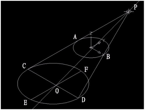
现在要画一个偏心圆锥,底面在WCS的XY平面上,圆心(0,0,0),半径100,顶点(300,0,400)在ZX平面上.
1)连接PA,PB. A(-100,0,0) B(100,0,0)

图1
在当前坐标下:
2)延长PA到C,使PA=CA;延长PB到D,使PB=DB;
3)连接CD;
4)以CD为直径画圆;
5)用XLINE命令中的二等分选项作角CPD的角平分线PO,交CD于O;
6)过O作CD的垂线,交圆于E,F;

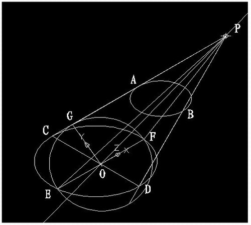
图2
7)用三点UCS命令,取三点为:O,P,C;
8)过点O作PO的垂线GO,交PC于G;

图3
9)再次用三点UCS命令,取三点为O,F,G;
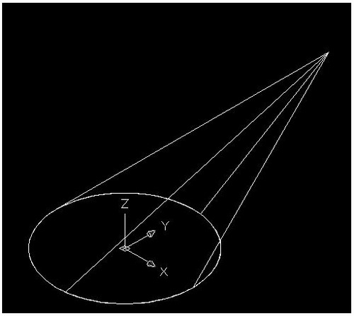
10)现在就可以画椭圆锥了!
cone-e-c-捕捉O点-捕捉F点-捕捉G点-a-捕捉P点;

图4
11)回到WCS,剖切椭圆锥
SL-选择椭圆锥-回车-XY-回车-捕捉P点.
12)删除辅助线条.

图5
说明:补充资料仅用于学习参考,请勿用于其它任何用途。
参考词条