1) blade size


刃口尺寸
1.
The principles of the calculation of blade sizes of blanking dies and their manufactured methods are introduced.
介绍了冲裁凸、凹模刃口尺寸计算原则和常用的冲模加工方法 ,给出了采用不同方法进行加工时冲裁模刃口尺寸的计算公式。
2) dimention of blanking die eages


冲裁刃口尺寸
4) toolmaker's straight edge


刃口平尺
6) gate dimension


浇口尺寸
1.
The relations of gate position to product shrinkage,gate dimension to facticity data of tensile strength and toughness of injection materials to mould cavity and ejector mechanism were stated.
简述了塑料测试试样浇口位置与制品收缩的关系,阐述了浇口尺寸与拉伸强度数据真实性的关系,以及注塑材料的韧性程度与型腔设计及顶出机构等关系,提出了解决问题的措施;还提出了从根本上解决厚制品收缩的方法——盆地修模法。
补充资料:工程图标准尺寸及坐标尺寸
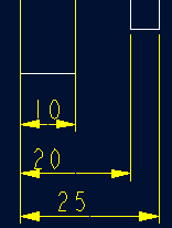
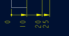
标准标注类型,是我们常用的标注类型。而坐标标注是便于数控加工采用的另一中标注形式。PRO/E可以将两种标注方式进行转换。
· 3.2 标准标注到坐标标注的转换
注意: 转化为坐标标注的尺寸必须是线性标注的,下列尺寸不能转化为坐标标注:
- 被显示成线性尺寸的直径
- 中心线尺寸
- 选择MODIFY DRAW > Dim Params > Dim Type > Ordinate Dim > Create Base.
- 选择作为参考基准线的尺寸
- 选择基准的引出线,该点为0点
- 选择 MOD DIM TYPE > Lin to Ord .
- 选择线性尺寸:注意:必须选择具有相同基准的尺寸
 ========>>>>
1. 选择 DIM PARAMS > Diam Dim Type .
2.点击Ord to Lin 
3.选择尺寸即可
说明:补充资料仅用于学习参考,请勿用于其它任何用途。
参考词条