1) Lack of Impartiality to Press a Curved Gou Piece

偏心压弯构件
2) eccentric compression member
偏心受压构件
1.
This paper presents calculation methods for reinforced concrete eccentric compression member with ring section, its contents are determination of longitudinal steel for new design member and calculation of carrying capacity for already reinforced members.
本文为钢筋混凝土环形截面偏心受压构件的计算,内容有纵向钢筋的确定、已配筋截面承载力的计算。
3) eccentrically compressed member
偏心受压构件
1.
In this paper, the defining methods of the bearing capacity (R) of a reinfoed concrete eccentrically compressed member are analysed and compared diagrammatically.
本文用图解方式对钢筋混凝土偏心受压构件承载力R的确定方法作了分析、比较。
4) compression members with large eccentricity
大偏心受压构件
1.
On the normal section design of doubly reinforced flexural members,tension members with large eccentricity and compression members with large eccentricity,the balanced section is designed in general,of which the equifinal depth of compression zone equals to the balanced depth of compression zone.
钢筋混凝土基本构件设计中,有两个问题值得商榷:(1)双筋受弯构件、大偏心受拉构件以及大偏心受压构件的正截面设计问题中的常见做法是在基于截面等效受压区高度等于界限高度时截面纵筋总配筋量最少的认识下将截面设计成界限截面,但根据推导,界限截面并不是纵筋总配筋量最少的条件,而且设计成界限截面还会丧失截面的延性,降低构件的可靠度。
6) compression member with small eccentricity
小偏心受压构件
1.
The paper presents an approximate method of calculating ξ by using a first order multinomial of best approximation to simplify the basic formula in section design of symmetric reinforcement for compression member with small eccentricity,which results indicate that the method was higher accuracy and relative lower error than that of code s formula.
对小偏心受压构件在对称配筋情况下的截面配筋计算,提出用最佳一次逼近多项式简化基本公式,直接按二次方程求解ξ的近似方法,具有精度高,相对误差小,计算方便等优点,可供工程设计人员参考。
补充资料:在AutoCAD中偏心圆锥与偏心圆台实体的画法
现在要画一个偏心圆锥,底面在WCS的XY平面上,圆心(0,0,0),半径100,顶点(300,0,400)在ZX平面上.
1)连接PA,PB. A(-100,0,0) B(100,0,0)

图1
在当前坐标下:
2)延长PA到C,使PA=CA;延长PB到D,使PB=DB;
3)连接CD;
4)以CD为直径画圆;
5)用XLINE命令中的二等分选项作角CPD的角平分线PO,交CD于O;
6)过O作CD的垂线,交圆于E,F;
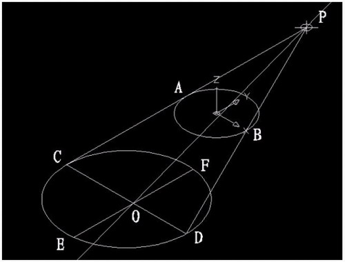
图2
7)用三点UCS命令,取三点为:O,P,C;
8)过点O作PO的垂线GO,交PC于G;

图3
9)再次用三点UCS命令,取三点为O,F,G;
10)现在就可以画椭圆锥了!
cone-e-c-捕捉O点-捕捉F点-捕捉G点-a-捕捉P点;
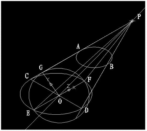
图4
11)回到WCS,剖切椭圆锥
SL-选择椭圆锥-回车-XY-回车-捕捉P点.
12)删除辅助线条.
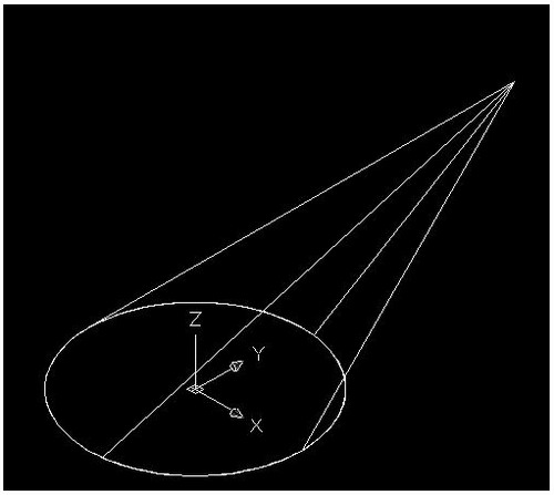
图5
说明:补充资料仅用于学习参考,请勿用于其它任何用途。
参考词条