1) planar crank-and-slider mechanism


平面曲柄滑块机构
1.
By introducing "Auxiliary Angle Method",this paper makes a deeper and systematic discussion on the analytical method of designing planar crank-and-slider mechanism simultaneously in accordance with K and ,and draws some significant conclusions.
引用"辅助角方法",对同时按K和[α]设计平面曲柄滑块机构的解析方法进行研究讨论,得出了如下重要结论:与"基本方程法"比较,"辅助角方法"更表现出良好的适应性和统一性,其在理论和公式的简约概括性,现象和规律的简洁直观性,现象、规律和结论的深刻、丰富和系统性方面,都表现出诸多具体实在的优越性。
2) planar crank-slider mechanism


平面曲柄滑块机构
1.
Chaos method for function synthesis of planar crank-slider mechanism;


平面曲柄滑块机构函数综合的混沌方法
3) planar crank and slider mechanism


平面曲柄滑块机构
1.
Based on the "Auxiliary Angle Method", this paper puts forward and solves the theoretical task for designing planar crank and slider mechanism with allowable transmission angle and most evident Quick-return Characteristics K max .
以“辅助角方法”为理论基础 ,提出并解决了按一并具有许用传动角 [γ]和最显著急回特性Kmax之条件设计平面曲柄滑块机构的理论课题 。
4) offset type planar crank and slider mechanisms


偏置式平面曲柄滑块机构
5) slider-crank mechanism


曲柄滑块机构
1.
Research on simulative experimental teaching of slider-crank mechanism;


曲柄滑块机构仿真实验教学的研究
2.
Research on position of maximum slider velocity in slider-crank mechanism;


曲柄滑块机构中滑块最大速度的位置探讨
3.
The expositions in the high-speed operation of the slider-crank mechanism will have great inertia in the process; there are also some common methods in part of a balanced and complete balance of inertial force.
论述了曲柄滑块机构在高速运转过程中会产生很大惯性力的原因,并提出了部分平衡惯性力和完全平衡惯性力的常见方法。
6) Crank-slider Mechanism


曲柄滑块机构
1.
Study on the kinematic simulation of crank-slider mechanism based on MSGC;


基于MSGC的曲柄滑块机构快速仿真研究
2.
Research on partial balance of inertia force for crank-slider mechanism;


曲柄滑块机构惯性力部分平衡的研究
3.
Position problems about the fixed hinge point of crank-slider mechanism;


关于曲柄滑块机构固定铰链点的位置问题
补充资料:机械原理:曲柄滑块机构
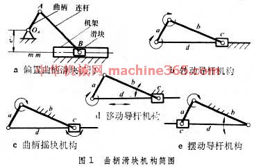
用曲柄和滑块来实现转动和移动相互转换的平面连杆机构﹐也称曲柄连杆机构。曲柄滑块机构中与机架构成移动副的构件为滑块﹐通过转动副A ﹑B 联接曲柄和滑块的构件为连杆(图1 曲柄滑块机构简图
 )。机构动动时﹐如铰链中心 B 的轨跡不通过曲柄的转动中心O ﹐称为偏置曲柄滑块机构(图1a 曲柄滑块机构简图 )﹐其中为偏距。如取不同的构件为机架﹐又可得到转动导杆机构(图1b 曲柄滑块机构简图 )﹑曲柄摇块机构(图1c 曲柄滑块机构简图 )和移动导杆机构(图1d 曲柄滑块机构简图)。如再将曲柄摇块机构中的导杆和滑块对换﹐即得到摆动导杆机构(图1e 曲柄滑块机构简图 )。如滑块B 的轨跡通过O ﹐则称为对心曲柄滑块机构(图2 对心曲柄滑块机构
 )。
)。 曲柄滑块机构广泛应用於往復活塞式发动机﹑压缩机﹑衝床等的主机构中。活塞式发动机以滑块为主动件﹐把往復移动转换为不整周或整周的迴转运动﹔压缩机﹑衝床以曲柄为主动件﹐把整周转动转换为往復移动。偏置曲柄滑块机构的滑块具有急回特性﹐锯床就是利用这一特性来达到锯条的慢进和空程急回的目的。对心曲柄滑块机构中(图2 对心曲柄滑块机构 )﹐当O A =AB 时﹐除D 点(AD =AB )的运动轨跡为直线外﹐连杆上其他点都沿椭圆轨跡运动﹐这种机构也称为椭圆仪。曲柄滑块的运动特性常用曲柄转角与滑块行程的关係曲线(图3 曲柄滑块机构简图运动特性
 )来表示。
)来表示。
说明:补充资料仅用于学习参考,请勿用于其它任何用途。
参考词条