1) combined milling cutter

片铣刀组
1.
The processing principle and method of slotting gear--grooves for big modulus gear wheel with combined milling cutter on a large--scale hobbing machine was put forward in the paper.
用片铣刀组粗切大模数齿轮齿槽的原理及其工艺。
2) milling insert

铣刀片
1.
Temperature field prediction for 3D complex slot typed milling insert based on artificial neural network;
基于人工神经网络的三维复杂槽型铣刀片温度场预测
2.
Study on force density function and stress field analysis of the waved-edge milling insert;
波形刃铣刀片受力密度函数的研究及其应力场分析
3.
Research on mathematical model of temperature field for milling insert with 3D complex groove;
三维复杂槽型铣刀片温度场数学模型研究
3) saw-tooth milling cutter

锯片铣刀
1.
The deformation and flaw of saw-tooth milling cutters happen frequently during the process of heat treatment.
锯片铣刀在热处理过程中常有变形、裂纹现象发生。
4) Disk milling cutter

片铣刀
5) group milling cutter

组合铣刀
6) Milling with inserted–tooth cutter

镶片铣刀盘铣削
补充资料:铣刀片的应力场分析
【摘要】 铣削属断续切削,切削过程中刀片受力非常复杂,力的大小和方向随时变化,刀片的失效形式主要为冲击破损。因此,采用有限元法对铣刀片应力场进行分析,以寻求减少刀片破损的刀具最佳几何角度,对于铣刀片槽型的开发具有指导意义。
1.引言
铣削属断续切削,切削过程中刀片受力非常复杂,力的大小和方向随时变化,刀片的失效形式主要为冲击破损。因此,采用有限元法对铣刀片应力场进行分析,以寻求减少刀片破损的刀具最佳几何角度,对于铣刀片槽型的开发具有指导意义。
2.面铣切削加工坐标系统的建立

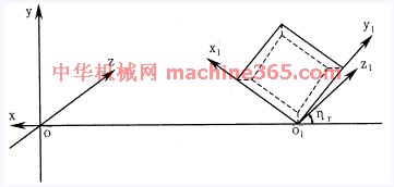
图1 面铣切削加工坐标系统
面铣切削加工坐标系统由刀体坐标系和刀片坐标系组成,如图1所示。
在刀体坐标系中,Y轴为铣刀轴线,X轴在基面内过刀尖与Y轴相交。在刀片坐标系中,y1轴通过主切削刃,x1轴通过副切削刃,刀片前刀面在x1o1y1平面内。铣刀半径为R=OO1,铣刀前角为g0,刃倾角为ls,主偏角为K,法向前角为gn。
面铣刀无论具有何种几何角度,都可看作是由刀体坐标系经过一次平移和三次旋转而成,可用矩阵表示为

其中 A11=cosgnsinhr+singnsinlscoshr
A12=cosgncoshr-singnsinlssinhr
A13=singncosls
A21=-coslscoshr
A22=coslssinhr
A23=sinls
A31=-singnsinhr+cosgnsinlscoshr
A32=-singncoshr-cosgnsinlssinhr
A33=cosgncosls
tggn=tgg0cosls

图2 切入冲击力的方向
3.切入冲击力方向的确定
铣削与车削的不同之处在于铣削为断续切削,存在着切入、切出过程,铣刀的破损主要是由机械冲击力引起的。因此,首先要确定铣刀切入瞬间冲击力的作用方向。铣削时,铣刀高速旋转,工件缓慢进给,若忽略进给运动(因进给运动速度仅为铣刀运动速度的约1/4),铣刀切入冲击力的方向应该在刀具相对工件运动的切线方向上。如图2所示。
由图1可知,切入冲击力方向为Z轴方向,力F分解到刀片坐标系中为

说明:补充资料仅用于学习参考,请勿用于其它任何用途。
参考词条


