1) Profile curve of the eccentric cam


偏心轮轮廓曲线
2) outline curve


轮廓曲线
1.
Double circular appoximating algorithm of outline curve;


轮廓曲线的双圆弧逼近算法
2.
Spectrum analysis of outline curve of body surface of earthworm and statistical model


蚯蚓体表轮廓曲线谱分析及统计模型
3.
Research on design method of a cam outline curve based on AutoCAD


基于AutoCAD的凸轮轮廓曲线设计方法研究
3) curve contour


曲线轮廓
1.
For machining sine-function curve contour,general using line or arc line to in NC,this paper briefly introduces approaching methods and programming,according to calculation of approaching node and approaching inaccuracy.
对于加工正弦函数曲线轮廓,一般要采用直线段逼近或圆弧段逼近的方法来实现加工。
4) contour curve


轮廓曲线
1.
Design of cam contour curve based on CAE technique;


基于CAE技术的凸轮轮廓曲线设计
2.
Designing and drawing contour curve of periphery cam with AutoCAD VBA;


用AutoCAD VBA设计盘形凸轮的轮廓曲线
3.
Cubic NURBS expression for contour curves of parallel indexing cam


平行分度凸轮轮廓曲线的三次NURBS表示
5) Profile curve


轮廓曲线
1.
This paper carried out a CAD animation design on cam profile curve of the cam mechanism with Oscillating Roller follower by using instantaneous velocity center on AutoCAD, so as to obtain cutter center track for milling disk-cam and pressure angle at any point of the profile.
在AutoCAD基础上利用速度瞬心进行摆动滚子从动件凸轮机构轮廓曲线的CAD动画设计 ,同时可以生成刀具中心的加工轨迹、计算出压力角 ,能够实现CAD/CAM一体化 ,是一种简捷实用的新方法 ,可以直接应用于生产实际和教
2.
This article introduces the computer-aided design method of the profile curve in parallel dividing cam with VB and the method how to draw the parallel dividing cam profile curve with AutoCAD in VB environments,and calculates the design error of the parallel dividing cam.
介绍了基于VB的平行分度凸轮轮廓曲线的计算机辅助设计,通过调用MATLAB实现了平行分度凸轮轮廓曲线设计误差的估计,介绍了在VB中调用AutoCAD绘制平行分度凸轮工作轮廓曲线的方法。
6) contour line offset


轮廓线偏置
1.
For rapid prototyping manufacturing (RPM), there are three main modules——real-time slicing module, contour line offsetting module and scanning route optimizing module.
通过研究快速原型 (RP)加工中的实时切片模块、轮廓线偏置模块和扫描路径优化模块 ,开发了 RP加工过程的计算机仿真系统 ,再现了 RP加工的实际情况 。
补充资料:在AutoCAD中偏心圆锥与偏心圆台实体的画法
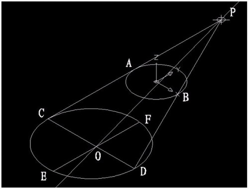
现在要画一个偏心圆锥,底面在WCS的XY平面上,圆心(0,0,0),半径100,顶点(300,0,400)在ZX平面上.
1)连接PA,PB. A(-100,0,0) B(100,0,0)

图1
在当前坐标下:
2)延长PA到C,使PA=CA;延长PB到D,使PB=DB;
3)连接CD;
4)以CD为直径画圆;
5)用XLINE命令中的二等分选项作角CPD的角平分线PO,交CD于O;
6)过O作CD的垂线,交圆于E,F;

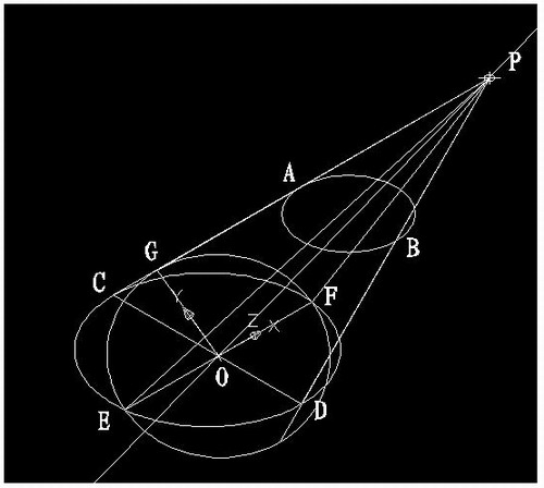
图2
7)用三点UCS命令,取三点为:O,P,C;
8)过点O作PO的垂线GO,交PC于G;

图3
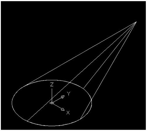
9)再次用三点UCS命令,取三点为O,F,G;
10)现在就可以画椭圆锥了!
cone-e-c-捕捉O点-捕捉F点-捕捉G点-a-捕捉P点;

图4
11)回到WCS,剖切椭圆锥
SL-选择椭圆锥-回车-XY-回车-捕捉P点.
12)删除辅助线条.

图5
说明:补充资料仅用于学习参考,请勿用于其它任何用途。
参考词条