1) internal profile controlling

层内调剖
1.
Using these models, it studies the potentiality of internal profile controlling of thick reservoirs, compares the effect of water flooding, polymer flooding and weak gel profile controlling in different permeability condition, and analyzes the effecting factors of deep profile controlling in different reservoir condition.
针对大庆油田厚油层地质特点 ,设计了不同的物理模型 ,并利用该模型研究了厚油层层内调剖的潜力以及不同渗透率下 ,水驱、聚合物驱与弱凝胶调剖的效果对比 ,并对不同油藏条件下的深部调剖影响因素进行了分析。
2) separate-zone profile correction
分层调剖
1.
Research and application of low shear separate-zone profile correction technology with polymer;
聚合物低剪切分层调剖工艺技术的研究与应用
3) profile control horizon
调剖层位
1.
Also, this article finds a formula to calculate the volume of profile control agent by method of reservoir engineering, achieve quantificational determination of profile control horizon and profile control agent volume.
结合油藏工程方法 ,建立了注聚前深度调剖井堵剂用量计算公式 ,实现了调剖层位及堵剂用量的定量化确定。
4) separate zone plugging and acidizing
分层调剖酸化
5) profile modification
调剖
1.
Field test of profile modification on produced sludge in Xingbei Oilfield;
杏北油田采出污泥调剖现场试验研究
2.
Integrated evaluation on reservoir profile modification suitability degree using fuzzy hierarchy determination;
应用模糊层次评判法进行油藏调剖适宜度综合评价
3.
Profile modification and profile modification plus oil displacement technique in the high water cut oilfield in Zhongyuan Oilfield;
中原高含水油田调剖、调驱技术研究
补充资料:全面解析在AutoCAD中模型的半剖.全剖.局部剖
在cad如何做些剖切呢.今日写了一个教程,抛砖引玉,希望给大家点思路.随便做了一个模型,下面就来发张图片
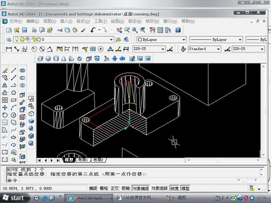
图1

图2
用剖切面完全剖开机件所得的剖视图称为全剖视图。全剖视图用于外形简单内部结构较复杂且不对称的机件。
全剖.操作要点:xy,.XZ,YZ等平面的剖面都是依据你的ucs坐标来的,因此如果某些时候剖切得不到全剖效果的话,那就你的坐标系有问题.
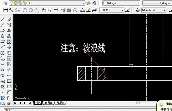
图3
最后选择b,保留两侧,得到全剖效果

图4

图5
半剖模型:
当机件具有对称平面时,在垂直于对称平面的投影面上投射所得的图形,以对称中心线为界,一半画成剖视图,另一半画成视图,这种剖视图称为半剖视图。半剖视图适用于内外结构都需要表达且具有对称平面的机件。
画半剖视图应注意:
(1)视图和剖视的分界线应是细点画线,不能以粗实线分界。
(2)半剖视图中由于图形对称,机件的内部形状已在半个剖视图中表示清楚,所以在表达外部形状的半个视图中不画虚线,以及在后方不可见的虚线都不画。
(3)机件的形状接近于对称,且不对称部分已另有图形表达清楚时,也可以画成半剖视图。
(4)当对称机件的轮廓线与中心线重合时,不宜采用半剖视图表示。
半剖的操作与阶梯剖有点相似.只不过阶梯剖的要做多条辅助线
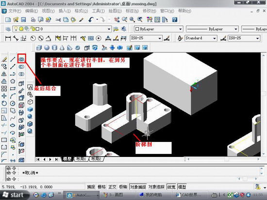
图6
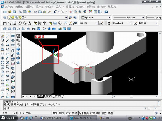
图7
局部剖:
用剖切面局部地剖开机件,以波浪线或双折线为分界线,一部分画成视图以表达外形,其余部分画成剖视图以表达内部结构,这样所得的图形称为局部剖视图。它用于内外结构都需要表达且不对称的机件。
说明:补充资料仅用于学习参考,请勿用于其它任何用途。
参考词条