1) self-propelled rotary cutting tool

自回转刀具
1.
Driven either by friction between cutter and workpiece or by an external power, the self-propelled rotary cutting tool turns around to produce continuous cutting edge, which can improve the cutting tool performance.
文中对自回转刀具的切削力和切削功率、切削温度、刀具磨损及耐用度、加工表面粗糙度等几个方面的研究现状加以综述,在此基础上探讨了今后自回转刀具的研究发展方向。
2) self-propelled rotary tool
自回转刀具
1.
The working principles and the structural features of the self-propelled rotary tools made of carbide alloys are discussed in this paper.
介绍了硬质合金自回转刀具工作原理及结构特点。
3) revolving cutter
回转刀具
1.
A novel design of the cutting edge is presented for solving the problem of traditional cutting edge of revolving cutters in the 2-axis ganged NC machining.
针对回转刀具传统刃口设计在二轴联动数控加工中遇到的问题,提出了解决这一问题的新型刃口设计原理,推导了相应的设计和虚拟制造的主干通用模型,并结合锥球头铣刀给出了应用实例。
2.
To solve the problem of traditional cutting edge design for revolving cutters in the 2-axis ganged NC machining,a novel cutting edge design is presented,the corresponding general main models for design and virtual manufacturing cutting edge of revolving cutters are deduced,and the applying example of ball-nosed cylindrical cutter is provided.
针对回转刀具传统刃口设计在二轴联动数控加工中遇到的问题,提出了解决这一问题的新型刃口设计原理,推导了相应的设计和虚拟制造的主干通用模型,并结合圆柱球头铣刀给出了应用实例。
3.
To solve the problem of traditional cutting edge design of revolving cutters in the 2 axis ganged NC machining, a novel cutting edge design method is put forward, and corresponding general main models for designing and virtual manufacturing cutting edge of revolving cutters are deduced, and a typical applying example is presented.
针对回转刀具传统刃口设计方法在二轴联动数控加工中遇到的问题 ,提出了回转刀具新型刃口设计方法 ,推导了相应的设计和虚拟制造主干通用模型 ,并给出了典型应用实
4) Research on Self-Propelled Rotary Tools
自回转刀具的研究
5) rotating tool
回转类刀具
1.
By the analysis of the most complicated part(cutter tooth) of rotating tool with multi-cutter tooth and spiral edge,the mathematics model,which can describe the geometry of spiral edge of rotating tool,is constituted and be used to establish isodiametric or varying diametric helical guidance locus.
通过对多齿螺旋刃回转类刀具建模难度最大的刀齿部分深入分析,建立了描述回转类刀具螺旋刃刀齿几何形状的数学模型,从而可以创建等径或不等径螺旋线导引轨迹。
6) rotary cutter
回转面刀具
1.
According to the forming principle of rotary helical flute surface, it is explained that the shaping process of rotary cutters by NC grinding is virtually the process to control the relative position and attitude and the relative motion direction in the space between the grinding wheel body and workpiece body at the every moment.
根据回转面刀槽螺旋面的成形原理 ,阐释了回转面刀具数控磨削成形的过程实质上就是控制每一瞬时砂轮几何体与工件几何体在空间的相对位姿和相对运动趋势的过程 ;分析了砂轮平动型和砂轮摆动型CNC工具磨床的运动形式 ,讨论了机床联动轴数的确定原则并给出了计算实
补充资料:刀具:锥齿轮加工刀具
专用於切削各种锥齿轮齿形的齿轮加工刀具。锥齿轮加工刀具按被切齿轮的种类可分为直齿锥齿轮刀具﹑弧齿锥齿轮刀具和延长外摆线锥齿轮刀具3类。
直齿锥齿轮刀具 主要有成对刨刀﹑成对铣刀盘﹑拉-铣刀盘和锥齿轮定装滚刀等(图1 直齿锥齿轮刀具 ) 。
。
成对刨刀 常用於加工模数为 0.3~20毫米的直齿锥齿轮。刨刀的齿形角等於被切齿轮的公称压力角﹐刀体上有前角﹐但无后角(见刀具)。工作后角是靠刨刀斜装於刀座而获得。加工时﹐两把刨刀分布在相邻齿槽内加工一个轮齿的两侧面。
成对铣刀盘 工作原理与成对刨刀基本相同(见齿轮加工)﹔但刀盘直径大(150~600毫米)﹑齿数多﹐生產率较刨齿高2~4倍。在加工齿轮时﹐齿数相等的两把铣刀盘在同一齿槽内分别切出左右侧面的齿形。但刀齿互相错开﹐一把铣刀盘的刀齿斜插在另一铣刀盘的两齿间。刀盘的直线切削刃分布在一个3°30左右的凹锥面上﹐因此能方便地切出鼓形齿﹐有利於嚙合。
拉-铣刀盘 用於加工模数为6毫米以下的直齿锥齿轮﹐刀盘直径为400~600毫米。刀体上装有15~17个扇形刀块﹐每块上有4~5个刀齿。粗切刀齿的顶刃逐渐昇高﹐齿昇量约为0.1毫米﹐它们逐渐地切入齿轮的齿槽直到全部深度﹐粗切刀齿部分最后7个刀齿的顶刃没有齿昇量﹐只用於修整齿槽的两侧面和槽底。粗切刀齿一般有18~20个﹐顶刃没有齿昇量。在精切刀齿前的缺口内﹐可安装一把成形刀﹐对齿顶进行倒角。拉-铣刀盘的切削是拉削和铣削的复合过程﹐是粗﹑精加工的混合过程。工作时刀盘一面旋转﹐同时作左﹑右往復移动。刀盘转一转可切好一个齿槽﹐生產率很高。拉-铣刀盘的刀齿均製成半径相等﹑但圆心位置不同的圆弧。刀齿是铲背的﹐用钝后刃磨前面。
锥齿轮定装滚刀 用於在具有专门附件的滚齿机上加工小模数等高齿直齿锥齿轮﹐一般有两个刀齿﹐相隔180°。它们在按一定的速比转动时﹐在两个不同的位置上分别切出齿槽的两侧。
弧齿锥齿轮铣刀盘 又称格利森 (Gleason)铣刀盘﹐用於加工模数为 0.5~15毫米的弧齿锥齿轮。常用的刀盘公称直径为12.7~457.2毫米(1/2~18英寸)﹐共有10个规格。12.7~50.8毫米(1/2~2英寸)的铣刀盘製成整体式﹐直径较大的製成镶齿式(图2 弧齿锥齿轮铣刀盘 )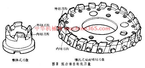 。铣刀盘可分为粗切刀盘和精切刀盘两类。粗切刀盘有双面(装有内切和外切两组刀齿)和三面(装有内切﹑外切和顶切三组刀齿)两种。精切刀盘有单面(仅有内切或外切中的一种刀齿)和双面两种。粗切刀盘要求刀齿多﹑刚性好﹐刀盘背后有支承环承受刀齿的切削力﹔精切刀盘要求精度高﹐有垫片和斜楔﹐可精确调整刀齿的径向位置。各种刀盘上的刀齿切削刃都是直线形﹐有一定的齿形角﹐刀齿须按计算的刀号选用﹐以得到正确的配对齿形﹐并採用铲背式﹐使刀齿重磨后的径向位置和齿形角保持不变。随著高效铣齿机的发展﹐出现了几种新型铣刀盘﹐如粗切用高刚性铣刀盘﹑楔装式铣刀盘﹐此外还有在半滚切法中加工大轮时採用的圆柱刀刀盘和螺旋成形法刀盘等。
直齿锥齿轮刀具 主要有成对刨刀﹑成对铣刀盘﹑拉-铣刀盘和锥齿轮定装滚刀等(图1 直齿锥齿轮刀具 )
。 成对刨刀 常用於加工模数为 0.3~20毫米的直齿锥齿轮。刨刀的齿形角等於被切齿轮的公称压力角﹐刀体上有前角﹐但无后角(见刀具)。工作后角是靠刨刀斜装於刀座而获得。加工时﹐两把刨刀分布在相邻齿槽内加工一个轮齿的两侧面。
成对铣刀盘 工作原理与成对刨刀基本相同(见齿轮加工)﹔但刀盘直径大(150~600毫米)﹑齿数多﹐生產率较刨齿高2~4倍。在加工齿轮时﹐齿数相等的两把铣刀盘在同一齿槽内分别切出左右侧面的齿形。但刀齿互相错开﹐一把铣刀盘的刀齿斜插在另一铣刀盘的两齿间。刀盘的直线切削刃分布在一个3°30左右的凹锥面上﹐因此能方便地切出鼓形齿﹐有利於嚙合。
拉-铣刀盘 用於加工模数为6毫米以下的直齿锥齿轮﹐刀盘直径为400~600毫米。刀体上装有15~17个扇形刀块﹐每块上有4~5个刀齿。粗切刀齿的顶刃逐渐昇高﹐齿昇量约为0.1毫米﹐它们逐渐地切入齿轮的齿槽直到全部深度﹐粗切刀齿部分最后7个刀齿的顶刃没有齿昇量﹐只用於修整齿槽的两侧面和槽底。粗切刀齿一般有18~20个﹐顶刃没有齿昇量。在精切刀齿前的缺口内﹐可安装一把成形刀﹐对齿顶进行倒角。拉-铣刀盘的切削是拉削和铣削的复合过程﹐是粗﹑精加工的混合过程。工作时刀盘一面旋转﹐同时作左﹑右往復移动。刀盘转一转可切好一个齿槽﹐生產率很高。拉-铣刀盘的刀齿均製成半径相等﹑但圆心位置不同的圆弧。刀齿是铲背的﹐用钝后刃磨前面。
锥齿轮定装滚刀 用於在具有专门附件的滚齿机上加工小模数等高齿直齿锥齿轮﹐一般有两个刀齿﹐相隔180°。它们在按一定的速比转动时﹐在两个不同的位置上分别切出齿槽的两侧。
弧齿锥齿轮铣刀盘 又称格利森 (Gleason)铣刀盘﹐用於加工模数为 0.5~15毫米的弧齿锥齿轮。常用的刀盘公称直径为12.7~457.2毫米(1/2~18英寸)﹐共有10个规格。12.7~50.8毫米(1/2~2英寸)的铣刀盘製成整体式﹐直径较大的製成镶齿式(图2 弧齿锥齿轮铣刀盘 )
。铣刀盘可分为粗切刀盘和精切刀盘两类。粗切刀盘有双面(装有内切和外切两组刀齿)和三面(装有内切﹑外切和顶切三组刀齿)两种。精切刀盘有单面(仅有内切或外切中的一种刀齿)和双面两种。粗切刀盘要求刀齿多﹑刚性好﹐刀盘背后有支承环承受刀齿的切削力﹔精切刀盘要求精度高﹐有垫片和斜楔﹐可精确调整刀齿的径向位置。各种刀盘上的刀齿切削刃都是直线形﹐有一定的齿形角﹐刀齿须按计算的刀号选用﹐以得到正确的配对齿形﹐并採用铲背式﹐使刀齿重磨后的径向位置和齿形角保持不变。随著高效铣齿机的发展﹐出现了几种新型铣刀盘﹐如粗切用高刚性铣刀盘﹑楔装式铣刀盘﹐此外还有在半滚切法中加工大轮时採用的圆柱刀刀盘和螺旋成形法刀盘等。 说明:补充资料仅用于学习参考,请勿用于其它任何用途。
参考词条