1) plugging and profile con-trol


封堵调剖
2) profile modifying and plugging


调剖和封堵
3) plug in profile-controlling water shutoff


调剖堵水封堵
4) profile control and water shutoff


调剖堵水
1.
Based on "2+3" theory of profile control and water shutoff, research on large dose multi-blocks deep profile control and oil displacement technique is put forward to improve injection profile and production profile.
为改善注水井吸水剖面和油井产液剖面,基于调剖堵水“2+3”理论提出了大剂量多段塞深度调驱技术。
2.
By profile control and water shutoff in Pucheng Oilfield, we got better effect and inquire into present situation of profile control, existing question and limited profilie control and water shutoff.
濮城油田通过开展调剖堵水取得了较好的效果。
5) profile control and water plugging


调剖堵水
1.
On the basis of static state geology research and water flooding research of oil reservoir engineering way,and full research heterogeneity of formation,water absorbing capacity and production performance,the software system of profile control and water plugging is developed.
调剖堵水优化设计软件是以油藏工程方法的静态地质研究和注水动态研究为基础 ,在充分研究了地层的非均质性、注水井的吸水剖面变化状况、注水井的吸水能力、周围油井生产动态的基础上 ,利用模糊综合评判技术提出了综合决策系统开发出的技术软件。
6) channeling block and profile control


堵窜调剖
补充资料:全面解析在AutoCAD中模型的半剖.全剖.局部剖
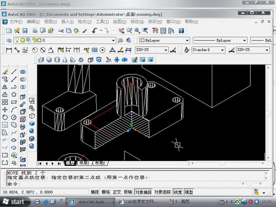
在cad如何做些剖切呢.今日写了一个教程,抛砖引玉,希望给大家点思路.随便做了一个模型,下面就来发张图片

图1

图2
用剖切面完全剖开机件所得的剖视图称为全剖视图。全剖视图用于外形简单内部结构较复杂且不对称的机件。
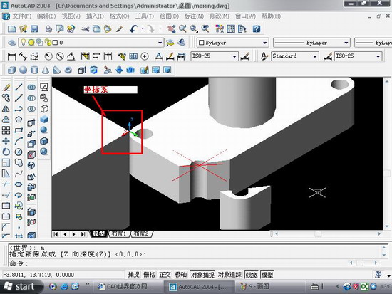
全剖.操作要点:xy,.XZ,YZ等平面的剖面都是依据你的ucs坐标来的,因此如果某些时候剖切得不到全剖效果的话,那就你的坐标系有问题.

图3
最后选择b,保留两侧,得到全剖效果

图4

图5
半剖模型:
当机件具有对称平面时,在垂直于对称平面的投影面上投射所得的图形,以对称中心线为界,一半画成剖视图,另一半画成视图,这种剖视图称为半剖视图。半剖视图适用于内外结构都需要表达且具有对称平面的机件。
画半剖视图应注意:
(1)视图和剖视的分界线应是细点画线,不能以粗实线分界。
(2)半剖视图中由于图形对称,机件的内部形状已在半个剖视图中表示清楚,所以在表达外部形状的半个视图中不画虚线,以及在后方不可见的虚线都不画。
(3)机件的形状接近于对称,且不对称部分已另有图形表达清楚时,也可以画成半剖视图。
(4)当对称机件的轮廓线与中心线重合时,不宜采用半剖视图表示。
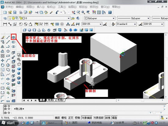
半剖的操作与阶梯剖有点相似.只不过阶梯剖的要做多条辅助线

图6

图7
局部剖:
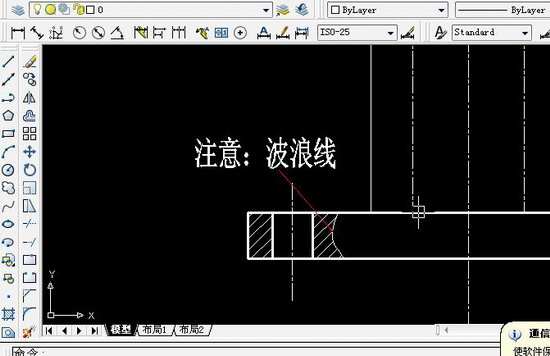
用剖切面局部地剖开机件,以波浪线或双折线为分界线,一部分画成视图以表达外形,其余部分画成剖视图以表达内部结构,这样所得的图形称为局部剖视图。它用于内外结构都需要表达且不对称的机件。
说明:补充资料仅用于学习参考,请勿用于其它任何用途。
参考词条