1) cutter eccentricity


刀具偏心
1.
The expression of instantaneous chip thickness is discussed by analyzing the effects of cutter eccentricity and deflection.
在Z-map仿真模型的基础上,提出了识别加工中参与切削的切削刃单元的方法,通过考虑刀具偏心和刀具变形对瞬时切削厚度的影响,推导出了瞬时切削厚度的表达式,由铣削力和切削负载之间的关系,建立了球头铣刀三轴铣削力仿真模型。
2.
Non-linear mathematical models of dynamic cutting force and cutting thickness are improved by considering influences of regenerative vibration theory and cutter eccentricity.
基于再生振动和刀具偏心对立铣加工过程的影响,建立了改进的动态切削力和切削厚度的非线性数学模型;利用计算机仿真技术,定量分析了上述因素对铣削加工振动和工件三维表面形貌的综合影响。
3.
The influence of cutter eccentricity parameters is considered and their expressions are deduced.
对数控加工中球头铣刀铣削力建模时刀具偏心参数的确定进行了研究。
2) cutter deflection


刀具偏心
1.
Mathematical models of cutting force,cutter deflection and cutting thickness resulted from regenerative chatter of an instant milling unit are deduced by studying on dynamics charcaters of up milling process.
研究逆铣加工过程动态特性,建立其铣削微元单位瞬态切削力、刀具偏心和再生振动引起的切削厚度数学模型。
2.
By considering synthetically influence of regenerative chatter theory and cutter deflection model on dynamic milling thickness, the formula of whole energy consumed in non-linear peripheral milling process is deduced.
综合考虑了再生振动效应与刀具偏心模型对动态铣削厚度的影响,建立了非线性立铣加工过程消耗能量表达式,以此作为目标函数提出了铣削振动状态预估与控制措施;利用铣削过程虚拟仿真系统对该方法的有效性和实用性进行了验证。
3.
In which the influence of regenerative chatter and cutter deflection model on dynamic milling process is considered comprehensively.
综合考虑再生振动效应和刀具偏心模型对动态铣削加工过程的影响,改进并建立具有较高预测精度的非线性圆周铣削力数学模型和铣削加工过程闭环控制系统。
3) of cutting tool's excursion


刀具偏移
1.
This paper makes a detailed introduction of the basic principles and implemental methods for the calculation of cutting tool's excursion on the basis of method.
本文详细介绍了r2法实现刀具偏移计算的基本原理和实施方法。
4) cutter arbor


刀具心轴
5) eccentric cutter holder


偏心刀架
6) plan (approach) angle


主偏角(刀具)
补充资料:在AutoCAD中偏心圆锥与偏心圆台实体的画法
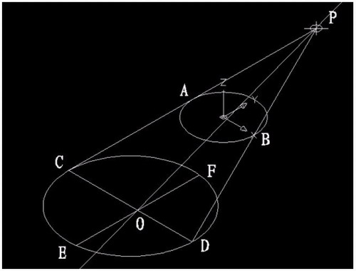
现在要画一个偏心圆锥,底面在WCS的XY平面上,圆心(0,0,0),半径100,顶点(300,0,400)在ZX平面上.
1)连接PA,PB. A(-100,0,0) B(100,0,0)

图1
在当前坐标下:
2)延长PA到C,使PA=CA;延长PB到D,使PB=DB;
3)连接CD;
4)以CD为直径画圆;
5)用XLINE命令中的二等分选项作角CPD的角平分线PO,交CD于O;
6)过O作CD的垂线,交圆于E,F;

图2
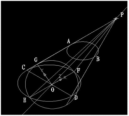
7)用三点UCS命令,取三点为:O,P,C;
8)过点O作PO的垂线GO,交PC于G;

图3
9)再次用三点UCS命令,取三点为O,F,G;
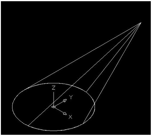
10)现在就可以画椭圆锥了!
cone-e-c-捕捉O点-捕捉F点-捕捉G点-a-捕捉P点;

图4
11)回到WCS,剖切椭圆锥
SL-选择椭圆锥-回车-XY-回车-捕捉P点.
12)删除辅助线条.

图5
说明:补充资料仅用于学习参考,请勿用于其它任何用途。
参考词条