1) eccentric gear


偏心齿轮
1.
Conjugate gear of eccentric gear and its design;


偏心齿轮的共轭非圆齿轮的设计
2.
Conjugate non-circular gear of eccentric gear and its involute tooth profile;


偏心齿轮的共轭非圆齿轮及其渐开线齿廓
3.
Based on SolidWorks,the entity model of the eccentric gear mechanism was builded,and the motion of eccentric gear mechanism was simulated by COSMOSMotion.
介绍了三维机械设计软件SolidWorks及其二次开发,并基于SolidWorks建立了偏心齿轮变速机构的实体模型,运用COSMOSMotion对其进行了运动仿真,得出相应的运动曲线,将以电子表格形式存放的动画模拟数据和理论分析数据做了一定的对比和分析,提高机构设计的直观性。
2) eccentric gear


偏心圆齿轮
1.
The tooth profile measurement of an eccentric gear;


偏心圆齿轮齿形误差的测量
3) eccentric rod gear


偏心轮杆齿轮
5) Modified eccentric circular gear


变形偏心圆齿轮
6) Eccentric involutes gear


偏心渐开线齿轮
1.
kinds of model of the analysis and design of eccentric involutes gears transmission are existed There are pure rolling model,equal truning angle model,bisection model and differential model.
偏心渐开线齿轮传动的设计和计算存在四种模型:纯滚动模型;等转角模型;等分模型和微分模型。
补充资料:在AutoCAD中偏心圆锥与偏心圆台实体的画法
现在要画一个偏心圆锥,底面在WCS的XY平面上,圆心(0,0,0),半径100,顶点(300,0,400)在ZX平面上.
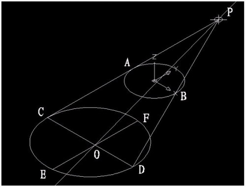
1)连接PA,PB. A(-100,0,0) B(100,0,0)

图1
在当前坐标下:
2)延长PA到C,使PA=CA;延长PB到D,使PB=DB;
3)连接CD;
4)以CD为直径画圆;
5)用XLINE命令中的二等分选项作角CPD的角平分线PO,交CD于O;
6)过O作CD的垂线,交圆于E,F;

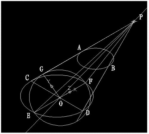
图2
7)用三点UCS命令,取三点为:O,P,C;
8)过点O作PO的垂线GO,交PC于G;

图3
9)再次用三点UCS命令,取三点为O,F,G;
10)现在就可以画椭圆锥了!
cone-e-c-捕捉O点-捕捉F点-捕捉G点-a-捕捉P点;

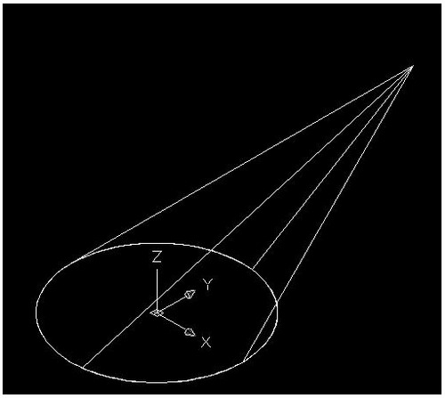
图4
11)回到WCS,剖切椭圆锥
SL-选择椭圆锥-回车-XY-回车-捕捉P点.
12)删除辅助线条.

图5
说明:补充资料仅用于学习参考,请勿用于其它任何用途。
参考词条