1) depth profile control


深度调剖
1.
Research of depth profile control technology in polymer flooding.;


聚合物驱深度调剖技术研究
2.
Application of pre-crosslinked gel particles to depth profile control.;


预交联凝胶微粒在深度调剖中的应用
3.
Based on lab tests, numerical analog and field tests in Pubei area, the effect of crosslinked polymer depth profile control on IOR has been analyzed in this paper in respect to the change of target bed of profile control in profile control well, fluid entry profile of non-target bed and production performance of the test area.
以室内实验和数值模拟研究为基础,根据葡北地区矿场试验情况,从调剖井调剖目的层、非目的层吸液剖面以及试验区生产动态等方面的变化,对交联聚合物(CD剂)深度调剖对提高采收率的作用进行了较为深入的分析。
2) deep profile control


深度调剖
1.
Compound plug deep profile control with low-cost alkali soil;


低成本碱土复合段塞深度调剖技术研究与应用
2.
Overview of deep profile control of polymer flooding in Daqing oilfield;


大庆油田聚合物驱深度调剖技术综述
3.
Experimental study of deep profile control by cross-linked polymer for micro fractured reservoir;
微裂缝油藏交联聚合物深度调剖试验研究
3) in-depth profile control


深度调剖
1.
This paper presents the gelling mechanism of the HPAM/AlCit CDG (colloidal dispersion gels), which is used in in-depth profile control before polymer flooding in oilfield for enhancing oil recovery, and factors of affecting the gelling, and the characteristic of flowing through the porous medium, and the effectiveness of the field test in Daqing Oilfield.
介绍了大庆油田应用胶态分散凝胶深度调剖技术的凝胶成胶机理、影响成胶的因素、凝胶在多孔介质中的渗流特征及现场试验效果 。
4) depth profile control agent


深度调剖剂
1.
A depth profile control agent based on oily sludge and some chemical agent has been developed.
在分析了油田采出液水处理过程中含油污泥组分和粒径的基础上 ,开发研制了以含油污泥体系为主要原料并添加适当化学助剂为辅加剂的含油污泥深度调剖剂。
5) waterflood depth profile control


水驱深度调剖
1.
4 water-injection wells were selected to carry waterflood depth profile control and evaluation.
本文综合运用多种测试方法,识别高渗透条带,优选出四口注水井进行水驱深度调剖,并对调剖井进行评价。
补充资料:全面解析在AutoCAD中模型的半剖.全剖.局部剖
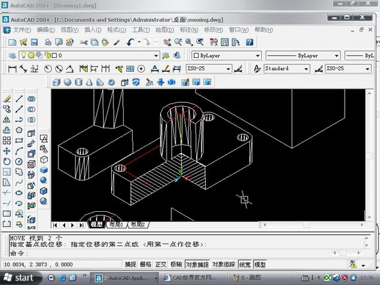
在cad如何做些剖切呢.今日写了一个教程,抛砖引玉,希望给大家点思路.随便做了一个模型,下面就来发张图片

图1

图2
用剖切面完全剖开机件所得的剖视图称为全剖视图。全剖视图用于外形简单内部结构较复杂且不对称的机件。
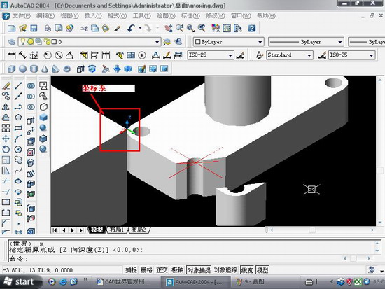
全剖.操作要点:xy,.XZ,YZ等平面的剖面都是依据你的ucs坐标来的,因此如果某些时候剖切得不到全剖效果的话,那就你的坐标系有问题.

图3
最后选择b,保留两侧,得到全剖效果

图4

图5
半剖模型:
当机件具有对称平面时,在垂直于对称平面的投影面上投射所得的图形,以对称中心线为界,一半画成剖视图,另一半画成视图,这种剖视图称为半剖视图。半剖视图适用于内外结构都需要表达且具有对称平面的机件。
画半剖视图应注意:
(1)视图和剖视的分界线应是细点画线,不能以粗实线分界。
(2)半剖视图中由于图形对称,机件的内部形状已在半个剖视图中表示清楚,所以在表达外部形状的半个视图中不画虚线,以及在后方不可见的虚线都不画。
(3)机件的形状接近于对称,且不对称部分已另有图形表达清楚时,也可以画成半剖视图。
(4)当对称机件的轮廓线与中心线重合时,不宜采用半剖视图表示。
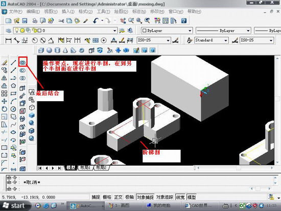
半剖的操作与阶梯剖有点相似.只不过阶梯剖的要做多条辅助线

图6

图7
局部剖:
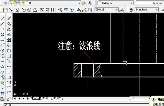
用剖切面局部地剖开机件,以波浪线或双折线为分界线,一部分画成视图以表达外形,其余部分画成剖视图以表达内部结构,这样所得的图形称为局部剖视图。它用于内外结构都需要表达且不对称的机件。
说明:补充资料仅用于学习参考,请勿用于其它任何用途。
参考词条