1) thin wall shell


薄壁壳体件
2) large complicated shell


薄壁壳体
1.
Wall thickness variation during multi-pass spinning of large complicated shell;


大型复杂薄壁壳体多道次旋压过程中的壁厚变化
3) thin shell die cast


薄壁壳形件
1.
By means of evacuating directly from the cavity of die can solve many problems in magnesium alloy thin shell die cast formation,such as long flow path and difficult to fill.
利用模内直接抽真空的方法可以解决镁合金薄壁壳形件流程长、填充型腔困难的问题,同时可减少镁合金的氧化和内部气孔、提高压铸件致密度、减小变形和达到高的表面质量要求。
4) the thin wall integral structure


整体薄壁件
1.
So the vibration of the thin wall integral structure is an urgent problem in the aviation machining industry.
铣削过程中的颤振是高速铣削实现高速、高效和高精度加工的关键限制因素之一,因此大型整体薄壁件高速铣削下的稳定性预测问题成为航空工业制造技术中迫切需要解决的技术难题。
5) complex thin shell


复杂薄壁壳体
1.
The temperature and stress fields during quenching of the complex thin shell were numerically calculated with ANSYS finite element software.
采用ANSYS有限元软件对复杂薄壁壳体淬火过程温度场和应力场进行了数值计算,将通过有限元法计算的工件外表面畸变量与实测值进行了对比。
6) complicated thin-walled shell


异型薄壁壳体
1.
FEA of power spinning of complicated thin-walled shell based on orthogonal optimization;


基于正交优化的异型薄壁壳体强力旋压成形有限元分析
2.
Some key technologies during the modeling process have been solved at the first, including the determination of initial position and roller path, and the implementation of the definition of blank thickness which is variable etc, and then based on software ABAQUS/Explicit, a 3D elastic-plastic dynamic explicit FEM model for the power spinning of complicated thin-walled shell has been established.
基于ABAQUS/Explicit平台,在解决建模过程中有关旋轮定位、旋轮运动轨迹确定、连续变壁厚坯料壁厚定义的实现等关键问题的基础上,建立了异型薄壁壳体强力旋压三维弹塑性动态显式有限元模型。
补充资料:薄壁件拉深切边模
在冲压生产中,经常遇到无凸缘壁件的拉深加工,如果薄壁件形状较为复杂,在冲模设计中就要解决两个主要问题:(1)因出料要求凹模不能采用整体形状,但由于工件开头复杂,凹模需整体加工,这个矛盾在设计中应予以考虑。(2)由于拉深件下料进要留出修边量,故在拉深后应有切边工序,无论在车床上用专用夹具加工还是留修边最后磨削加工,都趣在效率低,易破坏工件外形等问题。
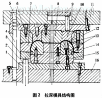
我厂生产的YJH256液力变矩器泵轮外环(见图1),就属于此种类型零件,为适应生产需要,设计了如图2所示的拉深模具。
我厂生产的YJH256液力变矩器泵轮外环(见图1),就属于此种类型零件,为适应生产需要,设计了如图2所示的拉深模具。


1.下接盘 2.顶杆 3.压料板 4.导向装置 5.连接圈 6.上接盘 7.凹模板 8.压块 9.上出料装置 10.退料圈 11.上模座 12.凸模 13.下出料装置 14.切边环 15.凸模座 16下模座
工作原理:(1)顶杆2推出压料板3,压在凹模块7上。(2)凹模整体(凹模块7,连接圈5,上接盘6,压块8,退料圈10,上模座11)下降,工件成形,降至切边环刃处,切掉凸缘。(3)凹模抬起,同时油压机上缸活塞顶出,上出料装置9下压退料圈10下行,工件退出凹模。(4)下出料装置13中的弹簧顶出推杆,将切边余料从切边环上退出。
设计中的注意事项:(1)由于出料要求,凹模采用分体式,但要整体加工,故退料圈10应现与上接盘6配钻螺孔,装配后与凹模块7一起进行车削。(2)连接圈5与凹模块7制成分体式,凹模块磨损后可更换。(3)切边环采用工具钢制造,要求淬火,并采用见风使快换嵌入式。(4)此装置应带有导向机构。
说明:补充资料仅用于学习参考,请勿用于其它任何用途。
参考词条